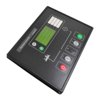
DSE Model 5210 Automatic Start Engine Management and Instrumentation System Operators Manual
8.3.3 PERKINS 2800 SERIES
PLUG “A” 8 WAY
52xx
PIN No
52xx
DESCRIPTION
Perkins Customer interface
connector
NOTES
4 Fuel relay output 1, 10, 15, 33, 34 Powers up ECU and enables the
injectors.
5 Start relay output - Connects directly to engine starter
solenoid.
PLUG “C” 3 WAY
52xx
PIN No
52xx
DESCRIPTION
Perkins Customer interface
connector
NOTES
20 CANbus common - Screen for the J1939 cable. Connect at
52xx end only.
21 CANbus H 31
J1939 + Use only screened 120Ω
impedance cable approved specifically
for use in CANbus applications.
22 CANbus L 32
J1939 - Use only screened 120Ω
impedance cable approved specifically
for use in CANbus applications.
NOTE:- According to Perkins, warning lamps or equivalent must be connected to Perkins customer
interface connector terminals 3, 4, 5, 8, 9, 16, 17. Failure to connect to these terminals will results in
“open circuit” alarms from the ECU. Perkins have advised that a suitable equivalent for the warning lamp
is a 220Ω 5W resistor. Be aware that outputs on terminals 4,5, & 16 are battery positive outputs. The
outputs on terminals 3, 6, 8, 9 & 17 are battery negative outputs.
5210 OPERATING MANUAL ISSUE 2 21/05/2003 AM
36