DSE Model 5210 Automatic Start Engine Management and Instrumentation System Operators Manual
15.4 J1939 CANBUS INTERFACE (OPTIONAL)
M
C
odules fitted with the J1939 CANbus interface (specify on ordering) are capable of receiving engine data
from engine CANbus controllers compliant with the J1939 standard.
anbus enabled engine controllers monitor the engines operating parameters such as engine speed, oil
pressure, engine temperature (among others) in order to closely monitor and control the engine. The data that is
gathered by the engine controller is transmitted on an industry standard communications interface (Canbus J1939).
This allows generator controllers such as the DSE 52xx range to access these engine parameters with no physical
connection to the sensor device.
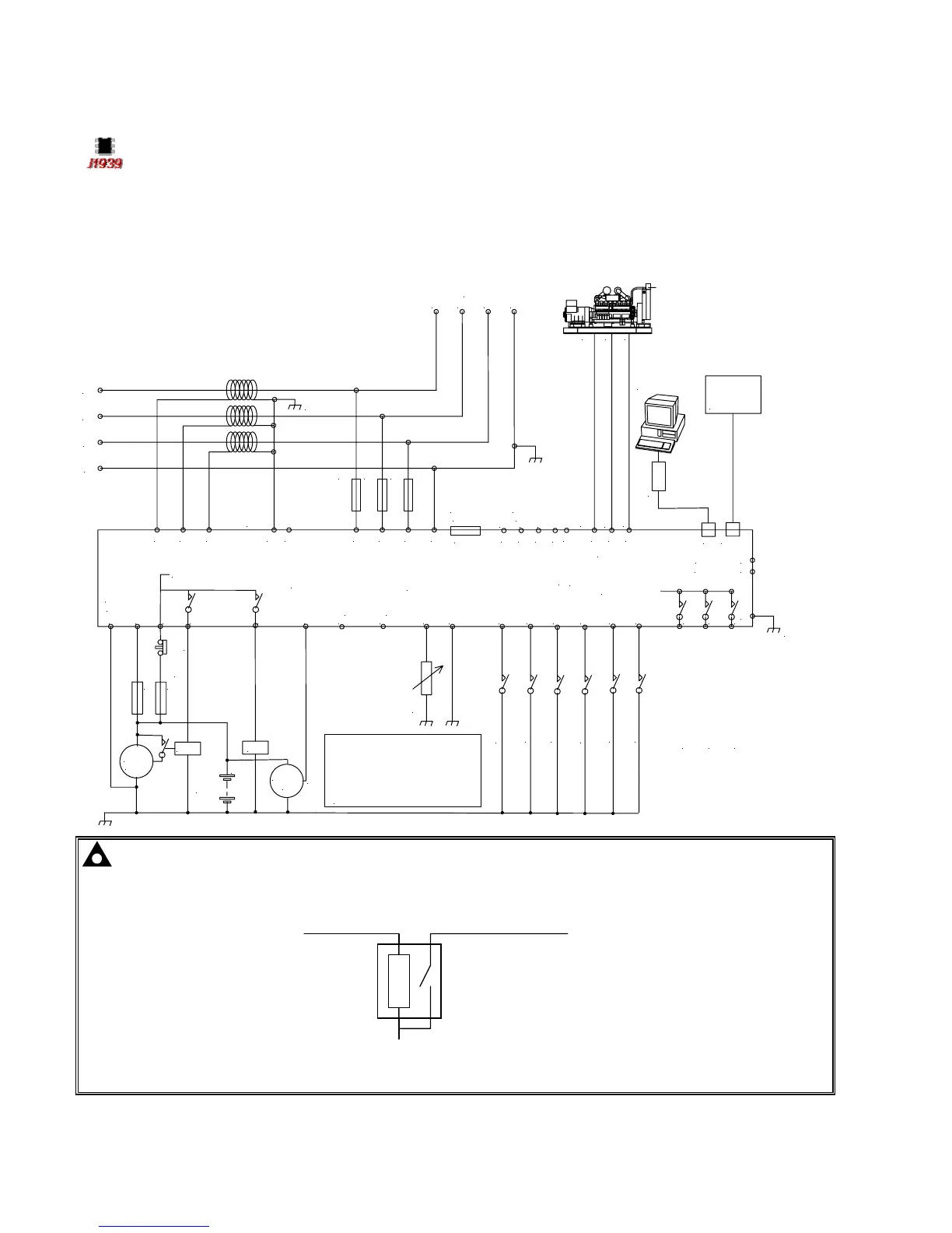
15.4.1 EXAMPLE OF CONNECTING 5210 CONTROLLER TO ENGINE CANBUS.
To plant supply +ve
Crank
Starter
motor
Battery
Charge
alt.
WL
F
F
Fuel
Emergency
stop
internal emergency stop
Configurable auxiliary input 1
Configurable auxiliary input 2
Configurable auxiliary input 3
Configurable auxiliary input 4
Configurable auxiliary input 5
L1
L2
L3
N
LOAD
F2A F2A F2A
+
Supply for
controller
L1 L2 L3 N
These ground connections must be
on the engine block and must be
a sound electrical connection
to the sender bodies.
The ground connection to terminal 47
must not be used to provide a ground
connection to any other device.
Fuel level sender
RS485
Optional
9 way D
Optional
RS232
5210 controller
CanBus
Not connected
Output expansion
157 relay board
or
548 annunciator
5200 series
configuration software
810 interface
810
157/548
Functional
Earth
17
18
16
6 7 8
1413
12
11
10474645449
4
531 2
39 40 41 42
43
CT
common
CT
Earth
35 36 37 38
20 21 22
23
24
25
26
Configurable auxiliary input 6
15
Configurable auxiliary output 1
Configurable auxiliary output 2
Configurable auxiliary output 3
SCR A
B
COM
H
L
Not connected
Not connected
19
Not connected
Not connected
Not connected
Not connected
COM
H
L
NOTE:- Many CanBus ECU modules require a reset signal to clear any present alarms before the
engine can be restarted. A signal for this can be generated by configuring one of the 52xx modules
auxiliary outputs to “System in Stop Mode”. Depending upon the ECUs input requirements, an interposing
relay may be required ie
52xx output (system in stop mode) CanBus ECU RESET input
Automotive or
plug-in relay
Battery negative
For details on the requirements of your engine ECU with regards to ‘Reset’ , you are referred to the
manufacturer of your engine ECU.
5210 OPERATING MANUAL ISSUE 2 21/05/2003 AM
52