DSE Model 5210 Automatic Start Engine Management and Instrumentation System Operators Manual
5.1 TYPICAL LCD DISPLAY SCREENS
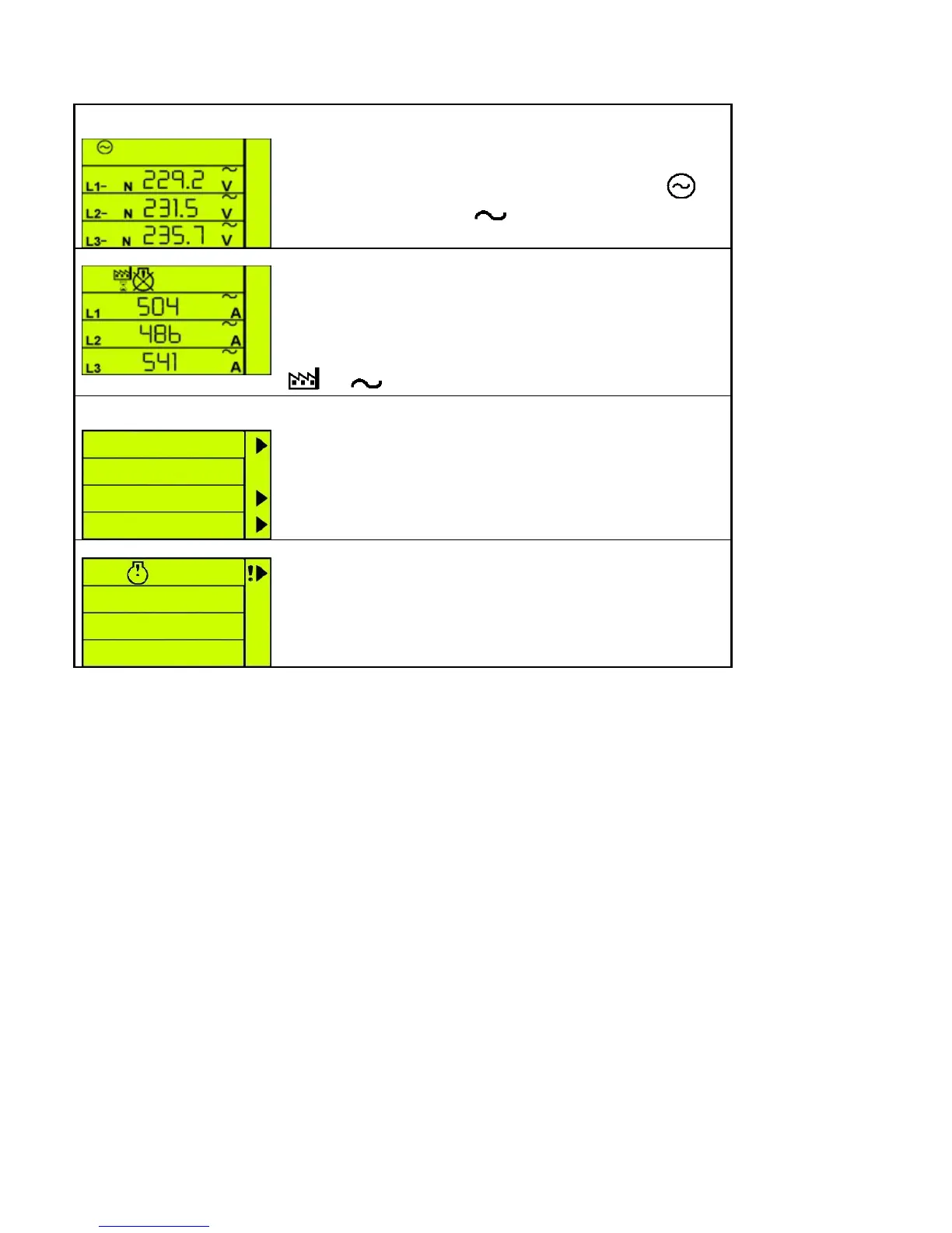
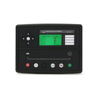
INSTRUMENTS
The LCD displays the various engine parameters such as ‘ENGINE
SPEED’, ‘OIL PRESSURE’, ‘HOURS RUN’, etc.
Each instrument is displayed with the appropriate units of measure.
In this example, the values being displayed are Generator
phase to neutral
L1-N, AC voltages V.
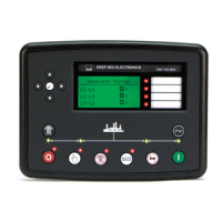
STATUS ICONS
The LCD also displays the status of the controller by showing (for
example) an hourglass symbol when a timer is in progress or by
displaying a common alarm symbol. This display is indicating that
the timer is in progress and a warning alarm is present. See the
‘Protections’ section of this manual for details of the alarms.
In this example the values being displayed are the three factory
AC currents A
USER DEFINED
INDICATIONS
The LCD displays the user-defined indications when configured
and active. The icons will illuminate and point to the appropriate
text insert label. These indications can be used to indicate the
operation of external equipment (i.e. ‘Battery Charger On’, ‘Breaker
Closed’ etc) or to indicate internal states (i.e. Engine Running,
Safety On, etc).
USER DEFINED ALARMS
The LCD displays the user-defined alarms when configured and
active. The icons will illuminate and point to the appropriate text
insert label. These alarms can be used to indicate the operation of
external alarms (i.e. ‘Low Fuel Level’, ‘Low Coolant level’ etc) or to
indicate internal alarms (i.e. Fail to Stop, MPU fault, etc).
5210 OPERATING MANUAL ISSUE 2 21/05/2003 AM
16