DSE Model 5210 Automatic Start Engine Management and Instrumentation System Operators Manual
15 APPENDIX
15.1 ALTERNATIVE WIRING TOPOLOGIES
The 5200 series controllers can support many different wiring topologies (AC systems) to suit the many systems in
use world-wide. The ‘Typical connection diagram’ details how to connect the module when used in a 3 phase, 4
wire system (3 phase star connected alternators). Changes to this typical wiring diagram for other AC systems are
detailed below.
NOTE:- The factory default configuration for the 5210 module is for use with the 3 phase, 4 wire AC
system. If another system is to be used, the controller must be reconfigured using the 5200 series
configuration software.
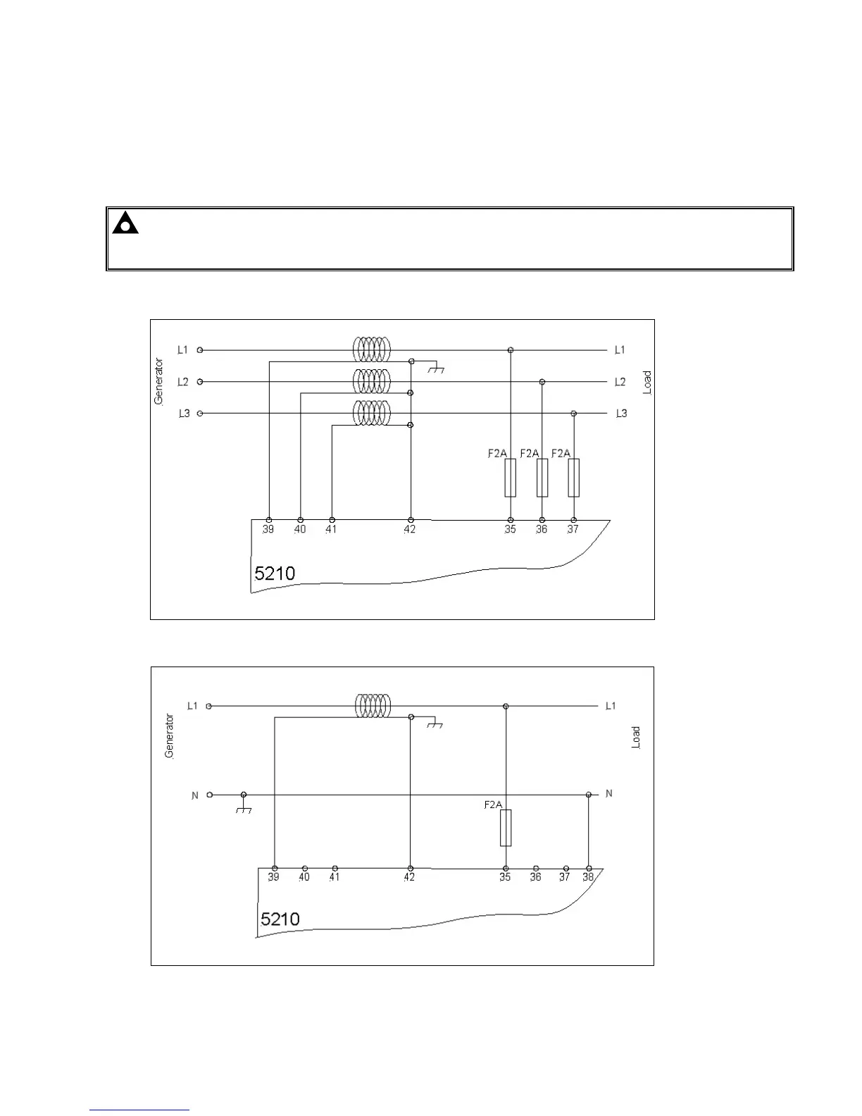
15.1.1 3 PHASE, 3 WIRE
The alternator is 3 phase delta connected. Phases are separated by 120°
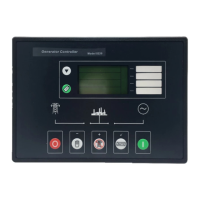
15.1.2 1 PHASE, 2 WIRE
Single phase alternator with neutral conductor.
47