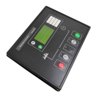
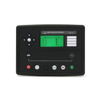
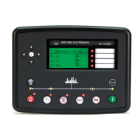
DSE Model 5210 Automatic Start Engine Management and Instrumentation System Operators Manual
8.3 ELECTRICAL CONNECTIONS TO J1939 ENABLED CONTROLLERS
This section of the manual is intended to describe only the connections between the 52xx controller and J1939
enabled controllers. All other connection details are described in the previous sections.
NOTE:- The CANbus specification, used by J1939, requires that a 120Ω terminator is fitted to each end of the
communications link. This termination resistor is fitted internally into the 52xx controller so is not required
externally. Ensure that the 52xx controller is the ‘last’ device on the communications link where more than one
device is connected to the engine ECU’s J1939 connector.
8.3.1 CUMMINS ISB / ISBE
PLUG “A” 8 WAY
52xx
PIN No
52xx
DESCRIPTION
Cummins ISB OEM Harness
connector B
NOTES
4 Fuel relay output 39 key switch input.
5 Start relay output - Connects directly to engine starter
solenoid.
6 Aux output 1 Use to control a 30A external
slave relay to supply DC battery
power to 01,07,12,13
Configure 52xx ‘aux op 1’ to be “Louvre
control” and configure 52xx ‘ETS Hold
Timer’ to 20 seconds. This is used to
power down the engine ECU 20seconds
after the set comes to rest.
PLUG “C” 3 WAY
52xx
PIN No
52xx
DESCRIPTION
Cummins ISB 9 pin Deutsch
connector
NOTES
SAE J1939 shield Screen for the J1939 cable. Connect at
Cummins ECU end only.
21 CANbus H SAE J1939 signal
J1939 + Use only screened 120Ω
impedance cable approved specifically
for use in CANbus applications.
22 CANbus L SAE J1939 return
J1939 - Use only screened 120Ω
impedance cable approved specifically
for use in CANbus applications.
5210 OPERATING MANUAL ISSUE 2 21/05/2003 AM
34