MAIN CONFIGURATION EDITOR PARAMETERS
NOTE: Depending upon module configuration, some values in the Main &
Running Configuration Editors may not be available. For more information refer to
DSE publication 057-243 DSE7310 MKII & DSE7320 MKII Configuraiton Suite PC
Software Manual available from www.deepseaplc.com
Parameter As Shown On Display
Current Date and Time Month, Year, hh:mm
Dual Mutual Mode
Engine Hours / Dual Mutual
Hours / Priority
Dual Mutual Duty Time 0 h 0 m
Editor
Config To Edit
Main Configuration /
Alternative Configuration
1,2,3,4,5
Default Configuration
Main Configuration /
Alternative Configuration
1,2,3,4,5
Engine
Oil Pressure Low Shutdown 0.00 bar
Oil Pressure Low Pre Alarm 0.00 bar
Coolant Temperature Low Warning 0 ºC
Coolant Temperature High Pre Alarm 0 ºC
Coolant Temperature High Electrical Trip 0 ºC
Coolant Temperature High Shutdown 0 ºC
Fuel Usage Alarm (Running Rate) 0 %
Fuel Usage Alarm (Stopped Rate) 0 %
Specific Gravity 0.00
Pre Heat Temperature 0 ºC
Post Heat Timer 0 h 0 m 0 s
Pre Heat Timer 0 h 0 m 0 s
Post Heat Temperature 0 ºC
Droop Control Active / Inactive
Engine Under Speed Shutdown Active / Inactive
Engine Under Speed Shutdown 0 RPM
Engine Under Speed Warning Active / Inactive
Engine Under Speed Warning 0 RPM
Engine Under Speed Delay 0.0 s
Engine Over Speed Warning Active / Inactive
Engine Over Speed Warning 0 RPM
Engine Over Speed Shutdown 0 RPM
Engine Over Speed Delay 0.0 s
Engine Speed Overshoot 0 %
Engine Speed Overshoot Delay 0.0 s
Battery Under Voltage Warning Active / Inactive
Battery Under Voltage Warning 0 V
Battery Under Voltage Warning Delay 0 h 0 m 0 s
Battery Over Voltage Warning Active / Inactive
Battery Over Voltage Warning 0 V
Battery Over Voltage Warning Delay 0 h 0 m 0 s
Charge Alternator Failure Warning Active / Inactive
Charge Alternator Failure Warning 0 V
Charge Alternator Warning Delay 0 h 0 m 0 s
Charge Alternator Failure Shutdown Active / Inactive
Charge Alternator Failure Shutdown 0.0 V
Charge Alternator Shutdown Delay 0 h 0 m 0 s
AC System 3 Phase, 4 Wire
Generator Under Voltage Shutdown 0 V
Generator Under Voltage Pre Alarm 0 V
Generator Under Voltage Delay 0.0 s
Generator Nominal Voltage 0 V
Generator Over Voltage Pre Alarm 0 V
Generator Over Voltage Shutdown 0 V
Generator Over Voltage Delay 0.0 s
Generator Under Frequency Shutdown 0.0 Hz
Generator Under Frequency Pre Alarm 0.0 Hz
Generator Under Frequency Delay 0.0 s
Generator Nominal Frequency 0.0 Hz
MAIN CONFIGURATION EDITOR PARAMETERS (CONTINUED)
Parameter As Shown On Display
Generator Over Frequency Pre Alarm 0.0 Hz
Generator Over Frequency Shutdown 0.0 Hz
Generator Under Frequency Delay 0.0 s
Generator Over Frequency Overshoot 0 %
Generator Over Frequency Overshoot
Delay
0.0 s
Generator CT Primary Current 0 A
Generator Secondary Current 1 A / 5 A
Generator CT Primary Earth Current 0 A
Delayed Over Current Active / Inactive
Generator Earth Fault Trip Active / Inactive
Generator Earth Fault Trip 0 %
Mains Under Voltage Trip 0 V
Mains Over Voltage Trip 0 V
Mains Under Frequency Trip 0.0 Hz
Mains Over Frequency Trip 0.0 Hz
Start Delay Off Load 0 h 0 m 0 s
Start Delay On Load 0 h 0 m 0 s
Start Delay Mains Fail 0 h 0 m 0 s
Start Delay Telemetry 0 h 0 m 0 s
Mains Transient Delay 0 m 0 s
Crank Duration Timer 0 m 0 s
Smoke Limiting 0 m 0 s
Smoke Limiting Off 0 m 0 s
Safety On Delay 0 m 0 s
Warm Up Timer 0 h 0 m 0 s
Transfer Time 0 m 0.0 s
Return Delay 0 h 0 m 0 s
Cool Down Timer 0 h 0 m 0 s
Fail To Stop Delay 0 m 0 s
LCD Page Timer 0 h 0 m 0 s
Auto Scroll Delay 0 h 0 m 0 s
Sleep Timer 0 h 0 m 0 s
Backlight Power Save 0 h 0 m 0 s
Schedule Active / Inactive
Schedule Bank 1 Period Weekly / Monthly,
On Load / Off Load / Auto Start Inhibit,
Week, Start Time, Run Time and Day
Selection (1-8)
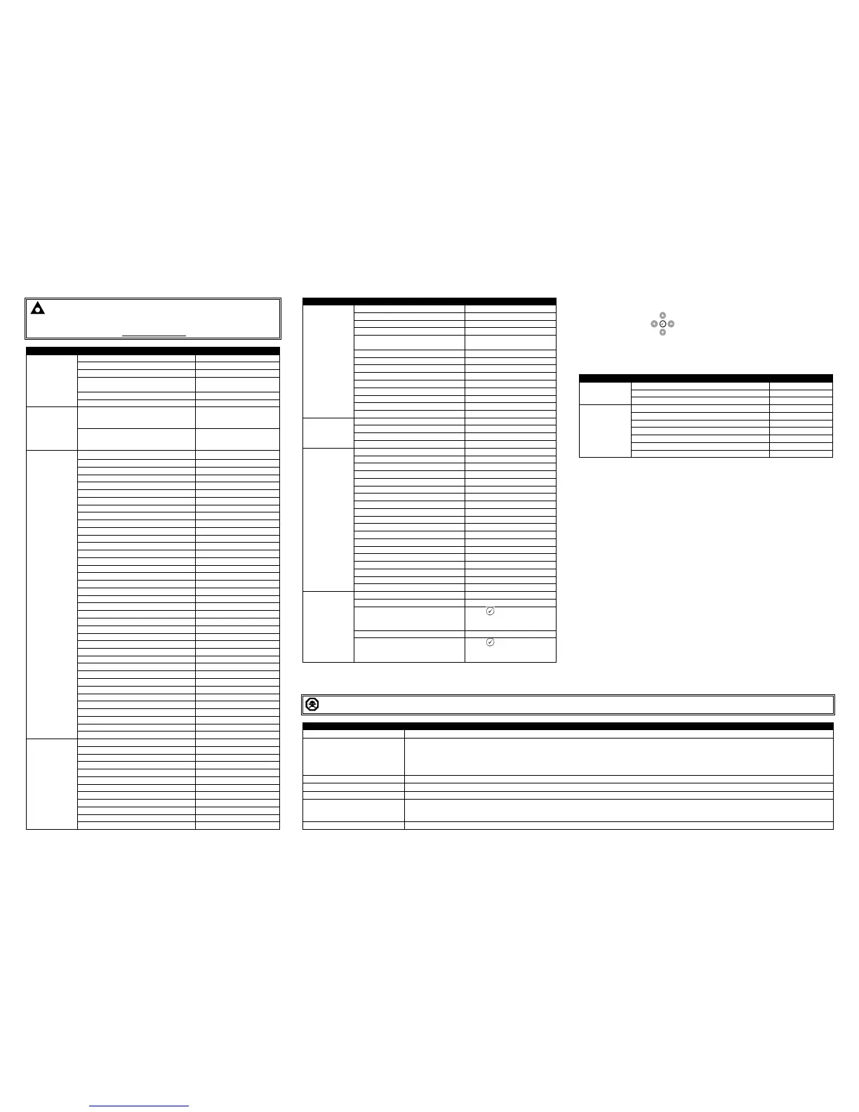
Press to begin editing then
up or down when selecting the
different parameters.
Schedule Bank 2 Period Weekly / Monthly,
On Load / Off Load / Auto Start Inhibit,
Week, Start Time, Run Time and Day
Selection (1-8)
Press to begin editing then
up or down when selecting the
different parameters.
ACCESSING THE ‘RUNNING’ CONFIGURATION EDITOR
• The ‘running’ editor can be entered while the engine is running. All protections remain
active if the engine is running while the running editor is entered.
• Press and hold the (Tick) button to enter the running editor.
RUNNING CONFIGURATION EDITOR PARAMETERS
Parameter As Shown On Display
Manual Frequency Trim 0.0 Hz
Speed Bias 0.0
Governor Gain 0
Frequency Adjust 0.0 %
DPF Auto Regen Inhibit Active / Inactive
DPF Manual Regeneration Request Active / Inactive
ECU Service Mode Active / Inactive
DIMENSIONS AND MOUNTING
245 mm X 184 mm X 51 mm
(9.6” X 7.2” X 2.0”)
220 mm X 160 mm
(8.7” X 6.3”)
Operating: -40 ºC to +70 ºC
(-40 ºF to +158 ºF)
Storage: -40 ºC to +80 ºC
(-40 ºF to +176 ºF)
QUIREMENTS FOR UL CERTIFICATION
WARNING!: More than one live circuit exists, see diagram overleaf for further information.
Screw Terminal Tightening Torque
4.5 lb-in (0.5 Nm)
Conductors
Terminals suitable for connection of conductor size 13 AWG to 20 AWG (0.5 mm² to 2.5 mm²).
• Conductor protection must be provided in accordance with NFPA 70, Article 240
• Low voltage circuits (35 V or less) must be supplied from the engine starting battery or an isolated secondary circuit.
• The communication, sensor, and/or battery derived circuit conductors shall be separated and secured to maintain at least ¼” (6 mm) separation from the
generator and mains connected circuit conductors unless all conductors are rated 600 V or greater.
Current Inputs
Must be connected through UL Listed or Recognized isolating current transformers with the secondary rating of 5 A max.
Communication Circuits
Must be connected to communication circuits of UL Listed equipment
DC Output Pilot Duty
Suitable for flat surface mounting in Type 1 Enclosure Type rating with surrounding air temperature -22 ºF to +122 ºF (-30 ºC to +50 ºC)
• Suitable for pollution degree 3 environments when voltage sensing inputs do not exceed 300 V. When used to monitor voltages over 300 V device to be
installed in an unventilated or filtered ventilation enclosure to maintain a pollution degree 2 environment.
Operating Temperature
-22 ºF to +122 ºF (-30 ºC to +50 ºC)
 Loading...