EasyManua.ls Logo

DEEP SEA ELECTRONICS DSE4510 MKII - User Manual

DEEP SEA ELECTRONICS DSE4510 MKII
2 pages
Print Icon
To Next Page IconTo Next Page
Loading...
Configuration Parameters Module (Page 1)
101
Contrast
0 (%)
121
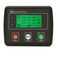
Generator Voltage Display
On (1), Off (0)
102
Fast Loading Enabled
On (1), Off (0)
122
Mains Voltage Display
On (1), Off (0)
103
All Warnings Latched
On (1), Off (0)
123
Generator Frequency Display
On (1), Off (0)
104
Lamp Test at Startup
On (1), Off (0)
124
Mains Frequency Display
On (1), Off (0)
105
Power Save Mode Enable
On (1), Off (0)
125
Current Display
On (1), Off (0)
106
Deep Sleep Mode Enable
On (1), Off (0)
126
kW Display
On (1), Off (0)
107
Protected Start Enable
On (1), Off (0)
127
kvar Display
On (1), Off (0)
108
Event Log Display Format
On (1), Off (0)
128
kVA Display
On (1), Off (0)
109
Power Up Mode
0 (Power Up Mode)
129
pf Display
On (1), Off (0)
110
DTC String Enable
On (1), Off (0)
130
kWh Display
On (1), Off (0)
111
RESERVED
131
kvarh Display
On (1), Off (0)
112
Pin Protected Maintenance
Reset
On (1), Off (0)
132
kVAh Display
On (1), Off (0)
113
Stop Button Cooldown
On (1), Off (0)
133
RESERVED
114
Use Module Oil Pressure
On (1), Off (0)
134
Show Load Switching Icons
On (1), Off (0)
115
Use Module Coolant Temp
On (1), Off (0)
135
Backlight Inactivity Timer
On (1), Off (0)
116
Use Module Engine Hours
On (1), Off (0)
136
ECU Periodic Wake Up
On (1), Off (0)
117
Use Module RPM
On (1), Off (0)
137
Coolant Temp Persistence
On (1), Off (0)
118
Use Module Charge Alt
On (1), Off (0)
138
Limit Audible Alarm Duration
On (1), Off (0)
119
Disable CAN Speed Control
On (1), Off (0)
139
Transducer Power Supply
On (1), Off (0)
120
CT Position
Gen (0), Load (1)
140
English Text Mode
On (1), Off (0)
Configuration Parameters CAN Application (Page 2)
CAN Alternative Engine Speed
On (1), Off (0)
203
CAN ECU Data Fail Action
0 (Action)
CAN ECU Data Fail Arming
0 (Arming)
204
CAN ECU Data Fail Delay
0 s
Configuration Parameters Digital Inputs (Page 3)
301
Digital Input A Source
0 (Input Source)
302
Digital Input A Polarity
0 (Polarity)
303
Digital Input A Action (If Source = User Config)
0 (Action)
304
Digital Input A Arming (If Source = User Config)
0 (Arming)
305
Digital Input A Activation Delay (If Source = User Config)
0 s
306
Digital Input B Source
0 (Input Source)
307
Digital Input B Polarity
0 (Polarity)
308
Digital Input B Action (If Source = User Config)
0 (Action)
309
Digital Input B Arming (If Source = User Config)
0 (Arming)
310
Digital Input B Activation Delay (If Source = User Config)
0 s
311
Digital Input C Source
0 (Input Source)
312
Digital Input C Polarity
0 (Polarity)
313
Digital Input C Action (If Source = User Config)
0 (Action)
314
Digital Input C Arming (If Source = User Config)
0 (Arming)
315
Digital Input C Activation Delay (If Source = User Config)
0 s
316
Digital Input D Source
0 (Input Source)
317
Digital Input D Polarity
0 (Polarity)
318
Digital Input D Action (If Source = User Config)
0 (Action)
319
Digital Input D Arming (If Source = User Config)
0 (Arming)
320
Digital Input D Activation Delay (If Source = User Config)
0 s
Configuration Parameters Outputs (Page 4)
401
Digital Output A Source
0 (Output Source)
407
Digital Output D Source
0 (Output Source)
402
Digital Output A Polarity
0 (Output Polarity)
408
Digital Output D Polarity
0 (Output Polarity)
403
Digital Output B Source
0 (Output Source)
409
Digital Output E Source
0 (Output Source)
404
Digital Output B Polarity
0 (Output Polarity)
410
Digital Output E Polarity
0 (Output Polarity)
405
Digital Output C Source
0 (Output Source)
411
Digital Output F Source
0 (Output Source)
406
Digital Output C Polarity
0 (Output Polarity)
412
Digital Output F Polarity
0 (Output Polarity)
Configuration Parameters Timers (Page 5)
501
Mains Transient Delay
513
ETS Solenoid Hold
Page Delay
502
Start Delay
514
Failed to Stop Delay
Cooling Time at Idle
503
Preheat Timer
515
Generator Transient Delay
Backlight Power Save Delay
504
Crank Time
516
Transfer Delay
Audible Alarm Timer
505
Crank Rest Time
517
Breaker Trip Pulse
Fuel Pull in Coil Duration
506
Smoke Limiting
518
Breaker Close Pulse
ECU Override Time
507
Smoke Limiting Off
519
Delayed Load Output 1
ECU Periodic Wakeup Period
508
DPF Ramp
520
Delayed Load Output 2
Post-Heat Timer
509
Safety On Delay
521
Delayed Load Output 3
Delay Crank Timer
510
Warm Up Time
522
Delayed Load Output 4
Max Star Pause Timer
511
Return Delay
523
Power Save Mode Delay
512
Cooling Time
524
Deep Sleep Mode Delay
Digital Input Polarity
Output Polarity
Alarm Action
Index
Polarity
Index
Polarity
Index
Action
0
Close to Activate
0
Energise
0
Electrical Trip
1
Open to Activate
1
De-Energise
1
Shutdown
2
Warning
AC System
Digital Input Alarm Arming
Power Up Mode
Index
Type
Index
Arming
Index
Mode
0
2 Phase 3 Wire (L1-L3)
0
Always
0
Stop
1
2 Phase 3 Wire (L1-L2)
1
From Safety On
1
Manual
2
3 Phase 3 Wire
2
From Starting
2
Auto
3
3 Phase 4 Wire
3
Never
4
3 Phase 4 Wire (Delta)
5
Single Phase 2 Wire
Functionality in DSE4510 MKII & DSE4520 MKII
Functionality in DSE4520 MKII only.
Configuration Parameters Generator (Page 6)
601
Alternator Fitted
On (1), Off (0)
622
Over Frequency Warning Trip
0.0 Hz
602
Alternator Poles
0
623
Over Frequency Shutdown
Enable
On (1), Off (0)
603
Under Voltage Shutdown
Enable
On (1), Off (0)
624
Over Frequency Shutdown Trip
0.0 Hz
604
Under Voltage Trip Shutdown
0 V
625
Generator AC System
0 (AC
System)
605
Under Voltage Warning Enable
On (1), Off (0)
626
CT Primary
0 A
606
Under Voltage Warning Trip
0 V
627
CT Secondary
1 A, 5 A
607
RESERVED
628
Full Load Rating
0 A
608
Loading Voltage
0 V
629
Immediate Over Current Enable
On (1), Off (0)
609
Over Voltage Warning Enable
On (1), Off (0)
630
Delayed Over Current Alarm
Enable
On (1), Off (0)
610
Over Voltage Warning Return
0 V
631
Delayed Over Current Alarm
Action
0 (Action)
611
Over Voltage Warning Trip
0 V
632
Over Current Delay Time
0 s
612
Over Voltage Shutdown Trip
0 V
633
Over Current Trip
0 %
613
Under Frequency Shutdown
Enable
On (1), Off (0)
634
kW Rating
0 kW
614
Under Frequency Shutdown Trip
0.0 Hz
635
Over kW Protection Enable
On (1), Off (0)
615
Under Frequency Warning
Enable
On (1), Off (0)
636
Over kW Protection Action
0 (Action)
616
Under Frequency Warning Trip
0.0 Hz
637
Over kW Protection Trip
0 %
617
RESERVED
638
Over kW Protection Trip Delay
0 s
618
Loading Frequency
0.0 Hz
639
Enable CT Support
On (1), Off (0)
619
Nominal Frequency
0.0 Hz
640
Over kW Protection Return
0 %
620
Over Frequency Warning
Enable
On (1), Off (0)
641
Nominal Voltage
0 V
621
Over Frequency Warning Return
0.0 Hz
Configuration Parameters Mains (Page 7)
701
Mains AC System
0 (AC System)
709
Over Voltage Level Trip
0 V
702
Mains Failure Detection
On (1), Off (0)
710
Under Frequency Enable
On (1), Off (0)
703
Immediate Mains Dropout
On (1), Off (0)
711
Under Frequency Trip
0.0 Hz
704
Under Voltage Enable
On (1), Off (0)
712
Under Frequency Return
0.0 Hz
705
Under Voltage Level
0 V
713
Over Frequency Enable
On (1), Off (0)
706
Under Voltage Return
0 V
714
Over Frequency Return
0 Hz
707
Over Voltage Enable
On (1), Off (0)
715
Over Frequency Trip
0.0 Hz
708
Over Voltage Return
0 V
Configuration Parameters Engine (Page 8)
801
Start Attempts
0
832
Start on Low Battery
Engine Run Duration
0 s
802
Over Speed Overshoot
0 %
833
RESERVED
803
Over Speed Delay
0 s
834
RESERVED
804
Gas Choke Timer
(Gas Engine Only)
0 s
835
J1939-75 Instruments Enable
On (1), Off (0)
805
Gas On Delay
(Gas Engine Only)
0 s
836
J1939-75 Alarms Enable
On (1), Off (0)
806
Gas Ignition Off Delay
(Gas Engine Only)
0 s
837
Engine CAN Source Address
0
807
Crank Disconnect On Oil
Pressure Enable
On (1), Off (0)
838
Instrumentation CAN Source
Address
0
808
Check Oil Pressure Prior to
Starting
On (1), Off (0)
839
RESERVED
809
Crank Disconnect On Oil
0.00 Bar
840
Tier 4 Home Screen Enable
On (1), Off (0)
810
Crank Disconnect On
Frequency
0.0 Hz
841
Start Pause Time
0 s
811
Crank Disconnect On Engine
Speed
0 RPM
842
Preheat Enable
On (1), Off (0)
812
Under Speed Enable
On (1), Off (0)
843
Preheat Temperature
0 °C
813
Under Speed Trip
0 RPM
844
Post-heat Enabled
On (1), Off (0)
814
Over Speed Trip
0 RPM
845
Post-heat Temperature
0 °C
815
Low Battery Voltage Enable
On (1), Off (0)
846
Coolant Heater Enabled
On (1), Off (0)
816
Low Battery Voltage Warning
0.0 V
847
Coolant Heater On Temp
0 °C
817
Low Battery Voltage Return
0.0 V
848
Coolant Heater Off Temp
0 °C
818
Low Battery Voltage Delay
0:00:00
849
Coolant Cooler Enabled
On (1), Off (0)
819
High Battery Voltage Enable
On (1), Off (0)
850
Coolant Cooler On Temp
0 °C
820
High Battery Voltage Return
0.0 V
851
Coolant Cooler Off Temp
0 °C
821
High Battery Voltage Warning
0.0 V
852
RESERVED
822
High Battery Voltage Warning
Delay
0 s
853
Tank Bund Level High Alarm
0 (Action)
823
Charge Alt Shutdown Enable
On (1), Off (0)
854
Fan Speed Low Arming
0 (Arming)
824
Charge Alt Shutdown Trip
0.0 V
855
Fan Speed Low Action
0 (Action)
825
Charge Alt Shutdown Delay
0 s
856
Fan Speed Low Delay
0 s
826
Charge Alt Warning Enable
On (1), Off (0)
857
Fuel Low Switch Arming
0 (Arming)
827
Charge Alt Warning Trip
0.0 V
858
Fuel Low Switch Action
0 (Action)
828
Charge Alt Warning Delay
0 s
859
Fuel Low Switch Activation
Delay
0 s
829
Start on Low Battery Enable
On (1), Off (0)
860
Crank Disconnect on Charge
Alt Enable
On (1), Off (0)
830
Start on Low Battery Threshold
0.0 V
861
Crank Disconnect on Charge
Alt Voltage
0.0 V
831
Start on Low Battery Start Delay
0 s
Configuration Parameters Analogue Inputs (Page 9)
901-902
RESERVED
903
Low Oil Pressure Enable
On (1), Off (0)
904
Low Oil Pressure Trip
0 Bar
905
Oil Pressure Sensor Open Circuit
On (1), Off (0)
906-907
RESERVED
908
High Engine Temperature Trip
0.00 °C
909
Temperature Sensor Open Circuit
On (1), Off (0)
910-929
RESERVED
930
Fuel Sensor C Low Alarm Action
Shutdown (2), Electrical Trip (1), Disabled (0)
931
Fuel Sensor C Low Shutdown Trip
0 %
932
Fuel Sensor C Low Shutdown Delay
0 s
933
Fuel Sensor C Low Pre-Alarm Enable
On (1), Off (0)
934
Fuel Sensor C Low Pre-Alarm Trip
0 %
935
Fuel Sensor C Low Pre-Alarm Return
0 %
936
Fuel Sensor C Low Pre-Alarm Delay
0 s
937
Fuel Sensor C High Pre-Alarm Enable
On (1), Off (0)
938
Fuel Sensor C High Pre-Alarm Return
0 %
939
Fuel Sensor C High Pre-Alarm Trip
0 %
940
Fuel Sensor C High Pre Alarm Delay
0 s
941
RESERVED
942
Fuel Sensor C High Alarm Action
Shutdown (2), Electrical Trip (1), Disabled (0)
943
Fuel Sensor C High Alarm Trip
0 %
944
Fuel Sensor C High Alarm Delay
0 s
945-967
RESERVED
968
Fuel Usage Alarm (Run) Arming
On (1), Off (0)
969
Fuel Usage Alarm (Run) Action
0 (Action)
970
Fuel Usage Alarm (Run) Trip
0 %
971
Fuel Usage Alarm (Run) Return
0 %
972
Fuel Usage Alarm (Stopped) Arming
0 (Arming)
973
Fuel Usage Alarm (Stopped) Action
0 (Action)
974
Fuel Usage Alarm (Stopped) Trip
0 %
975
Fuel Usage Alarm (Stopped) Return
0 %
976
Low Coolant Level Arming
0 (Arming)
977
Low Coolant Level Action
0 (Action)
978
Low Coolant Level Trip
0 %
979
Low Coolant Level Return
0 %
980
Low Coolant Level Delay
00:00:00
981
Low Coolant Level Open Circuit Arming
On (1), Off (0)
982
Low Coolant Level Switch Arming
0 (Arming)
983
Low Coolant Level Switch Action
0 (Action)
984
Low Coolant Level Switch Delay
00:00:00
985
High Engine Temp Pre-Alarm Enable
On (1), Off (0)
986
High Engine Temp Pre-Alarm Return
0.00 °C
987
High Engine Temp Pre-Alarm Trip
0.00 °C
Configuration Parameters Scheduler (Page 10)
1001
Enable Scheduler
On (1), Off (0)
1002
Schedule Run On or Off Load
On (1), Off (0)
1003
Scheduler Period
Weekly (0), Monthly (1)
1004, 1008, 1012, 1016, 1020, 1024, 1028, 1032
Start Time (Entry 1-8)
0:00:00
1005, 1009, 1013, 1017, 1021, 1025, 1029, 1033
Day (Entry 1-8)
0 (1=Monday)
1006, 1010, 1014, 1018, 1022, 1026, 1030, 1034
Week (Entry 1-8)
1, 2, 3 or 4
1007, 1011, 1015, 1019, 1023, 1027, 1031, 1035
Duration (Entry 1-8)
0 s
Configuration Parameters Time (Page 11)
1101
Time of Day
0:00:00
1104
Day of Month
1-31
1102
RESERVED
1105
Month of Year
1-12
1103
RESERVED
1106
Year
0-99
Configuration Parameters Maintenance Alarms (Page 12)
1201
Oil Maintenance Alarm Enable
On (1), Off (0)
1206
Air Maintenance Alarm Engine
Hours
0 h
1202
Oil Maintenance Alarm Action
0 (Action)
1207
Fuel Maintenance Alarm
Enable
On (1), Off (0)
1203
Oil Maintenance Alarm Engine
Hours
0 h
1208
Fuel Maintenance Alarm Action
0 (Action)
1204
Air Maintenance Alarm Enable
On (1), Off (0)
1209
Fuel Maintenance Alarm
Engine Hours
0 h
1205
Air Maintenance Alarm Action
0 (Action)
Configuration Parameters Alternate Configuration 1 (Page 20)
2001-2057
Refer to the DSE Publication 057-260 DSE4510 MKII & DSE4520MKII Operators Manual for
configuration parameters.
Configuration Parameters Alternate Configuration 2 (Page 30)
3002-3057
Refer to the DSE Publication 057-260 DSE4510 MKII & DSE4520MKII Operators Manual for
configuration parameters.
Configuration Parameters Alternate Configuration 3 (Page 40)
4002-4057
Refer to the DSE Publication 057-260 DSE4510 MKII & DSE4520MKII Operators Manual for
configuration parameters.
Question and Answer IconNeed help?

Do you have a question about the DEEP SEA ELECTRONICS DSE4510 MKII and is the answer not in the manual?

Overview

The DSE4510 MKII is a compact, auto-start control module designed to monitor engine parameters and provide protection for generator sets. It offers a comprehensive suite of features for both single-set and multi-set applications, ensuring reliable operation and easy management.

Function Description

The DSE4510 MKII functions as an engine and generator control module, capable of automatically starting and stopping the generator based on various inputs and conditions. It monitors a wide range of engine and generator parameters, including:

  • Engine Monitoring: Engine speed, oil pressure, coolant temperature, fuel level, battery voltage, and various engine alarms (e.g., overspeed, underspeed, low oil pressure, high engine temperature, low fuel, low/high battery voltage, charge alternator failure). It supports magnetic pick-up, CAN, and MPU/CAN combined for speed sensing.
  • Generator Monitoring: AC voltage (L-N, L-L), current (L1, L2, L3), frequency, and power (kW, kVA, kVAr, Power Factor). It can monitor up to three phases for voltage and current.
  • Protection Features: The module provides extensive protection, including overspeed, underspeed, low oil pressure, high engine temperature, low/high battery voltage, charge alternator failure, emergency stop, generator over/under voltage, generator over/under frequency, generator overcurrent, earth fault, reverse power, and loss of excitation. It also includes configurable warnings and shutdowns.
  • Control Features: Auto start/stop, manual start/stop, load transfer (configurable for various ATS types), pre-heat, post-heat, idle control, and configurable auxiliary inputs and outputs. It supports various crank disconnect methods, including frequency, oil pressure, and speed.
  • Event Log: The module maintains a comprehensive event log with date and time stamps, allowing for easy diagnostics and troubleshooting.
  • Scheduler: A built-in scheduler allows for up to 8 scheduled runs, configurable by date, time, and duration, which can be useful for maintenance or periodic testing.
  • CAN Engine Support: The DSE4510 MKII supports CAN engines, allowing for direct communication with engine ECUs to read engine parameters and fault codes. This includes support for various J1939 messages and diagnostic trouble codes (DTCs).
  • Configurable Inputs/Outputs: The module features configurable digital and analogue inputs, as well as digital outputs, allowing for flexible integration with various external devices and systems. Inputs can be configured as normally open, normally closed, or for various alarm conditions. Outputs can be configured for pre-heat, fuel solenoid, start solenoid, alarm outputs, and more.
  • Display and User Interface: A backlit LCD display provides clear visibility of all monitored parameters, alarms, and event logs. Navigation buttons allow for easy access to different screens and settings. The module also includes LED indicators for various statuses (e.g., Auto, Manual, Stop, Alarm).

Important Technical Specifications

  • Supply Voltage: 8 V to 35 V DC continuous.
  • Cranking Dropouts: Able to survive 0 V for 50 ms, providing supply was at least 10 V before dropout and supply recovers to 5 V.
  • Max. Operating Current: 160 mA at 12 V, 80 mA at 24 V.
  • Max. Standby Current: 80 mA at 12 V, 40 mA at 24 V.
  • Generator Voltage Input Range: 15 V to 333 V AC (Ph-N).
  • Generator Frequency Input Range: 3.5 Hz to 75 Hz.
  • Magnetic Pick-up Voltage Input Range: 0.5 V to 70 V RMS.
  • Magnetic Pick-up Frequency Input Range: 10 Hz to 10,000 Hz.
  • Charge Fail/Excitation Range: 0 V to 35 V.
  • Digital Inputs: Configurable as normally open or normally closed.
  • Analogue Inputs: Configurable for various sender types (e.g., VDO, Datcon, Faria, Murphy, resistive).
  • Outputs: Configurable for various functions, including fuel, start, pre-heat, and auxiliary alarms.
  • Dimensions:
    • Overall: 140 mm x 113 mm x 43 mm (5.5” x 4.4” x 1.7”).
    • Panel Cut-out: 118 mm x 92 mm (4.6” x 3.6”).
    • Maximum Panel Thickness: 8 mm (0.3”).
  • Operating Temperature: -30°C to +70°C (-22°F to +158°F).
  • Storage Temperature: -40°C to +85°C (-40°F to +185°F).
  • UL Certification: Suitable for use in Type 1 Enclosure. Low voltage circuits (35.5 V or less) must be supplied from the engine starting battery or an isolated secondary circuit. All conductors must be rated 75°C minimum.

Usage Features

  • User-Friendly Interface: The module features an intuitive interface with clear icons and a backlit LCD display, making it easy to navigate and monitor system status.
  • PC Configuration: The DSE Configuration Suite PC Software allows for comprehensive configuration of all module parameters, enabling customization to specific application requirements. This software provides a graphical interface for setting up inputs, outputs, alarms, engine parameters, and more.
  • Front Panel Editing: Basic parameters can be edited directly from the front panel of the module using the navigation buttons and the Auto Mode button for saving changes. This allows for quick adjustments without needing a PC.
  • Multi-Language Support: The module supports multiple languages, enhancing usability for a global audience.
  • Remote Monitoring: The DSE4510 MKII can be integrated with remote monitoring systems, allowing for off-site supervision and control of the generator set.
  • Flexible Configuration: The extensive configurability of inputs, outputs, and protection settings makes the module adaptable to a wide range of generator set applications and engine types.
  • Automatic Load Transfer: The module can be configured to automatically transfer load between the mains supply and the generator, ensuring continuous power in the event of a mains failure.
  • Engine Pre-Heat/Post-Heat: Configurable pre-heat and post-heat functions optimize engine starting and shutdown, extending engine life.
  • Idle Control: Supports engine idle control for specific applications.

Maintenance Features

  • Event Log: The detailed event log, accessible via the display or PC software, provides a historical record of all alarms, warnings, and operational events, aiding in troubleshooting and preventative maintenance.
  • Maintenance Scheduler: The built-in scheduler can be used to program periodic generator runs, which can be beneficial for exercising the generator and ensuring its readiness. It can also be configured to trigger maintenance alarms based on engine run hours or other criteria.
  • Engine Run Hour Counter: The module tracks engine run hours, which is crucial for scheduling routine maintenance tasks such as oil changes, filter replacements, and inspections.
  • Diagnostic Trouble Codes (DTCs): For CAN engines, the module can display active and logged DTCs, providing specific information about engine faults and simplifying diagnostics.
  • Alarm Indicators: Clear alarm indicators (LEDs and on-screen messages) provide immediate notification of issues, allowing for prompt intervention.
  • Service Alarms: Configurable service alarms can be set to trigger based on run hours, ensuring timely maintenance reminders.
  • Battery Monitoring: Continuous monitoring of battery voltage helps in identifying potential battery issues before they lead to starting problems.
  • Charge Alternator Failure Detection: The module detects charge alternator failures, ensuring that the battery is being properly charged.

The DSE4510 MKII is a robust and versatile control solution, designed to provide comprehensive monitoring, protection, and control for generator sets, while offering user-friendly operation and extensive diagnostic capabilities to simplify maintenance.

DEEP SEA ELECTRONICS DSE4510 MKII Specifications

General IconGeneral
BrandDEEP SEA ELECTRONICS
ModelDSE4510 MKII
CategoryController
LanguageEnglish

Related product manuals