Do you have a question about the DEEP SEA ELECTRONICS DSE4520 and is the answer not in the manual?
Details on installing the DSE4510 & DSE4520 modules.
Handout sheets for specific subjects during training sessions.
List of product manuals available for download from DSE website.
References to other relevant technical documents.
Defines short names used for DSE modules and ranges.
Specifies operating and storage temperature ranges for modules.
Details UL certification requirements for terminals, conductors, and circuits.
Details of the module's two-part connector and cable size limits.
Specifies voltage, current, and protection for module power supply.
Technical details for voltage and frequency measurement.
Technical details for current sensing measurements.
Guidance on CT VA rating based on cable distance and size.
Instructions for ensuring correct CT primary polarity.
Guidance on correct CT phase connection for accurate measurements.
Recommendations for selecting appropriate CT classes.
Details on digital and analogue input specifications.
Specifications for DC outputs and configurable outputs.
Details on USB and CAN communication port capabilities.
Configuration for using an external sounder with the module.
Information on engine hours run and accumulated power tracking.
Module dimensions, panel cutout, weight, fixing clips, and gasket.
List of standards the module conforms to, including IEEE C37.2.
Details on IP and NEMA enclosure protection ratings.
Overview and pin-out details for module terminals.
Wiring details for power supply, fuel, start, and configurable outputs.
Wiring information for analogue sensors like oil pressure and temperature.
Wiring for digital inputs and CAN communication ports.
Connection points for generator and mains voltage/frequency inputs.
Details on connecting current transformers for generator measurements.
Diagram and explanation of CT primary and secondary connections.
Information on connecting the module to a PC via USB.
Diagrams showing typical wiring for DSE4510 and DSE4520 modules.
Wiring diagrams for various generator and mains topologies.
Guidance on negative earth, positive earth, and floating earth systems.
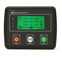
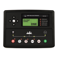
Explanation of the function of Stop/Reset, Auto, and Manual/Start buttons.
Icons used to indicate displayed instrumentation screens.
Icons indicating the active configuration selected on the controller.
Icons indicating the source of the auto start signal.
Icons indicating the current operating mode of the controller.
Icons indicating the status of generator and mains breakers.
Information on the LCD backlight behavior.
Icons displayed for warning, trip, and shutdown alarms.
Details of icons representing non-critical warning conditions.
Details of icons representing latching electrical trip alarms.
Details of icons representing latching shutdown alarms.
How to enter and navigate the module's menu system.
Scrolling through display pages using navigation buttons.
Information shown on the default home screen.
Display of electrical values for the generator.
Display of electrical values for the mains supply.
Display of electrical values related to load.
Display of engine parameters like speed, temperature, and oil pressure.
Information on module settings, scheduler, and software versions.
Viewing active Diagnostic Trouble Codes from the engine ECU.
Viewing recorded electrical trip or shutdown events and engine hours.
A brief guide to getting started with module operation.
Procedure for starting the generator engine.
Procedure for stopping the generator engine.
How to place the module into Stop/Reset mode and its functions.
Operation in automatic mode for unattended generator control.
Details the sequence for stopping the generator in auto mode.
Operation in manual mode for direct engine start and control.
Details on engine running and load transfer in manual mode.
How to stop the generator in manual start mode.
Configuration and management of engine maintenance alarms.
Using the built-in scheduler for automatic start/stop sequences.
Steps to enter and use the module's front panel configuration editor.
List and explanation of configurable parameters for module, CAN, inputs, outputs, and timers.
Parameters for configuring generator voltage, frequency, and protection.
Parameters for configuring mains voltage, frequency, and failure detection.
Parameters for engine operation, start/stop delays, and alarms.
Configuration of analogue inputs for sensors like oil pressure and temperature.
Configuration of scheduled start and stop times for the generator.
Setting the module's internal time and date.
Configuration of alarms for engine maintenance intervals.
Settings for alternate operating configurations.
Selection of input sources and output sources for module functions.
Defines actions for different alarm types (trip, shutdown, warning).
Sets the initial operating mode when the module powers up.
Selection of sensor types for analogue inputs.
Configuration of the AC system type (e.g., 3 Phase 4 Wire).
Configuration for when digital input alarms are armed.
Sets the polarity (close/open to activate) for digital inputs.
Sets the polarity (energise/de-energise) for digital outputs.
Selection of units for fuel level display (Litres, Gallons).
List of selectable pressure sensor types.
List of selectable temperature sensor types.
List of selectable percentage sensor types.
Troubleshooting steps for unit inoperative, fails to start, or starter issues.
Troubleshooting steps for generator not taking load or incorrect gauge readings.
Troubleshooting steps for various alarms like low oil pressure and high temperature.
Troubleshooting steps for CAN data link failures.
Troubleshooting steps for inaccurate generator measurements on display.
Troubleshooting steps for configuration reversion issues.
Part numbers for ordering additional connector plugs.
Part number for ordering module fixing clips.
Part number for ordering the module silicon sealing gasket.
Guidelines for the disposal of electronic equipment.
Information on hazardous substances and DSE's compliance.
| Display Type | LCD |
|---|---|
| Storage Temperature Range | -40 °C to +85 °C |
| Maximum Operating Altitude | 2000 m |
| Protection Rating | IP65 |
| Input Voltage | 8 to 35 V |
| Communication Ports | RS232, RS485 |