Installation – Terminal Description
27
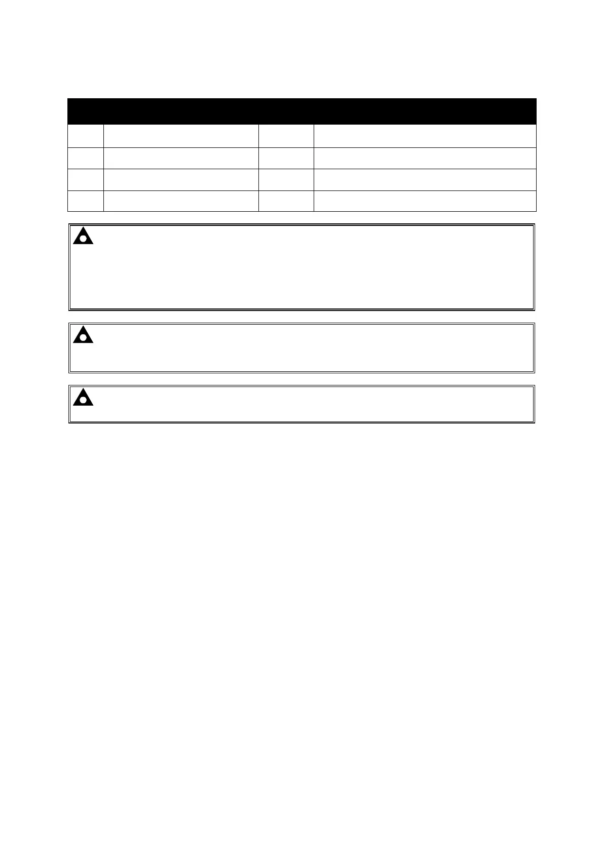
4.1.2 ANALOGUE SENSOR
Pin
No
Description
Cable
Size
Notes
10 Sensor Common Return
0.5mm²
AWG 20
Return Feed For Sensors
11 Oil Pressure Input
0.5mm²
AWG 20
Connect To Oil Pressure Sensor
12 Coolant Temperature Input
0.5mm²
AWG 20
Connect To Coolant Temperature Sensor
13 Fuel Level Input
0.5mm²
AWG 20
Connect To Fuel Level Sensor
NOTE: It is VERY important that terminal 10 (sensor common) is soundly connected to an
earth point on the ENGINE BLOCK, not within the control panel, and must be a sound
electrical connection to the sensor bodies. This connection MUST NOT be used to provide an
earth connection for other terminals or devices. The simplest way to achieve this is to run a
SEPARATE earth connection from the system earth star point, to terminal 10 directly, and not
use this earth for other connections.
NOTE: If you use PTFE insulating tape on the sensor thread when using earth return
sensors, ensure you do not insulate the entire thread, as this will prevent the sensor body
from being earthed via the engine block.
NOTE: For further details of module configuration, refer to DSE Publication: 057-172
DSE45xx Configuration Software Manual.