Installation – Terminal Description
25
4 INSTALLATION
The module is designed to be mounted on the panel fascia. For dimension and mounting details, see
the section entitled Specification, Dimension and mounting elsewhere in this document.
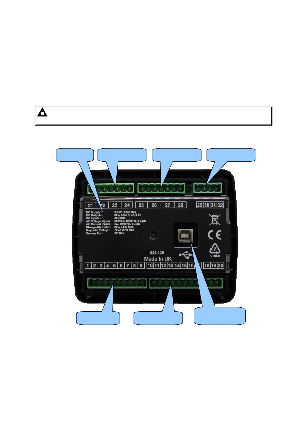
4.1 TERMINAL DESCRIPTION
To aid user connection, icons are used on the rear of the module to help identify terminal functions.
An example of this is shown below.
NOTE: Availability of some terminals depends upon module version. Full details are
given in the section entitled Terminal Description elsewhere in this manual.
Terminals 1-9 Terminals 10-20
Terminals 21-24 Terminals 29-32
USB
PC Configuration
Terminals 25-28 UL Ratings