Viewing The Instrument Pages
39
5.2 MODULE DISPLAY
The module’s display contains the following sections. Description of each section can be viewed in
the sub sections.
NOTE: Depending upon the module’s configuration, some display screens may be
disabled. For further details of module configuration, refer to DSE Publication: 057-172
DSE45xx Configuration Software Manual.
Inst.
Icon
Instrumentation
Unit
Alarm
Icon
Active
Config
Instrumentation
Unit
Mode
Icon
FPE /
Auto
Run
Instrumentation
Unit
Load Switching Icons
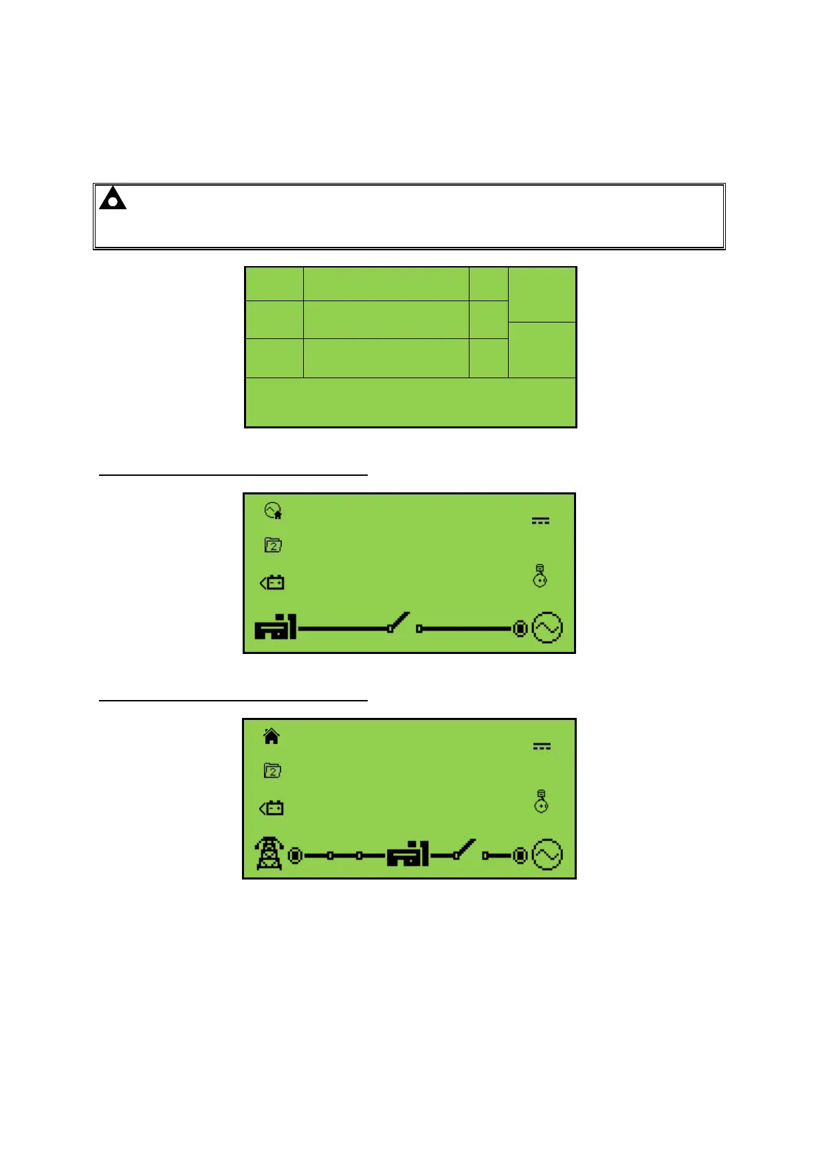
Example of DSE4510 Home Page Display
L1N
230
V
L2N
230
V
L3N
230
V
Example of DSE4520 Home Page Display
230
V
L1N
230
V
230
V
L2N
230
V
230
V
L3N
230
V