Boat
GB
23
10
6
1
2
5
1
15
3
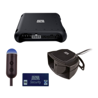
4. POWER SUPPLY
Cable marked 3: Is connected to the plus (positive) power cable when the ignition is
turned on, and when the motor is started (the starter motor turns)! If this is connected
incorrectly, the immobilizer will not work.
Cable marked 2: Ground. Is connected to the ground point on the motor block.
Cable marked 1:
Power supply. Is connected directly to the boat’s battery through a 1A fuse.
OR:
Is connected to the plus cable on the starter motor through a 1A fuse. (If this alternative
connection is used, the LED will not ash when the main power is turned off.)
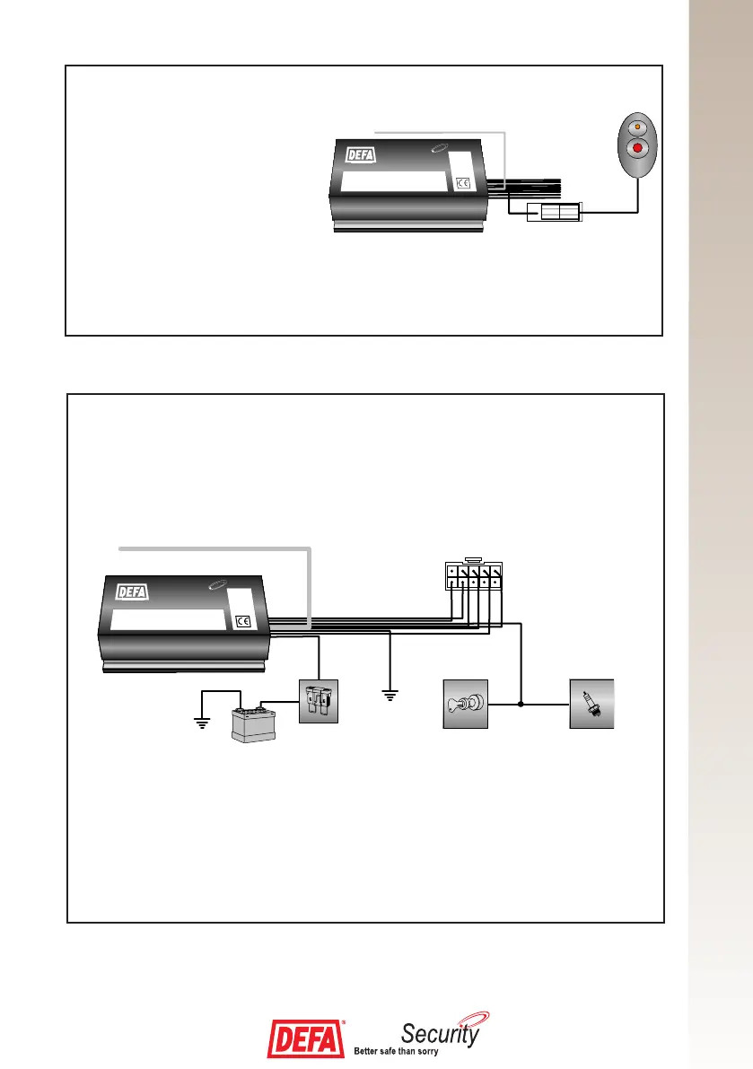
3. INSTALLING THE PIN CODE PANEL
Position the PIN code panel on the
instrument panel in a position easily
visible from the outside, which offers
easy access to the button. The PIN
code panel can also be tted on the
motor housing.
The plug from the PIN code panel
must be connected to the plug in the
wiring loom from the central unit.