Page 6 of 11 Tel.: (+45) 9614 9614 • Fax: (+45) 9614 9615 • E-mail: deif@deif.com
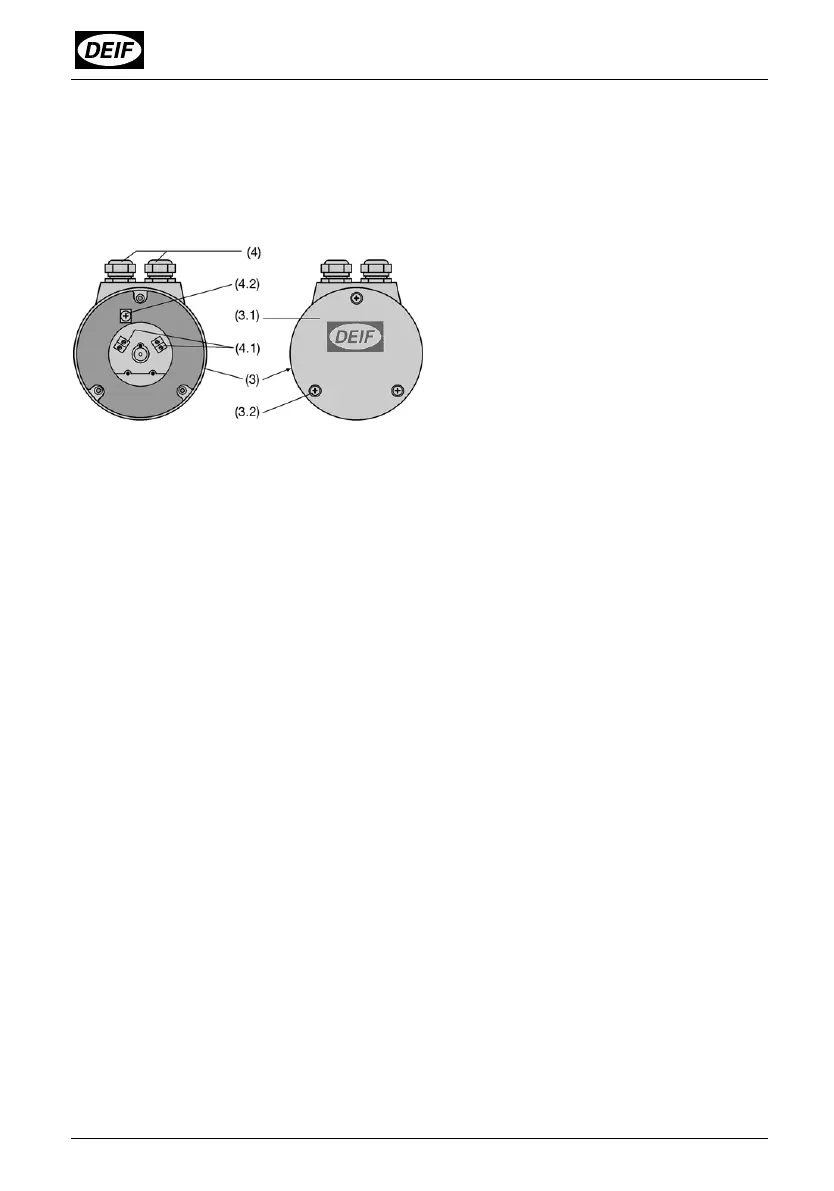
5. Connecting transmitter with screw terminals and cable glands
The transmitter is fitted with screw terminals and cable glands. There are 4 screw
terminals (4.1) plus 1 ground terminal (4.2) which are accessible after removing the
cover (3.1) (see Fig. 3). The maximum wire gauge the terminals can accept is 1.5
mm
2
.
Fig. 3
Rear (3) with terminals (4.1) and (4.2)
and cable glands (4).
Right: Cover (3.1) closed.
Left: Exposed.
Remove the 3 screws (3.2) and take off the cover (3.1).
Undo the gland nut and remove the pinch ring and seal from the gland opening. Place
these parts over the cable in the correct order and pass the end of the cable through
the gland hole into the rear of the transmitter.
Strip the insulation to a suitable length of the leads and connect them to the terminals
(4.1) and (4.2) according to the wiring diagram (Fig. 3).
Then fit the gland seal, pinch ring and nut. Tighten the gland nut and replace the
cover.