Installation instructions, RT-2
Page 5 of 11 4189350013C (UK)
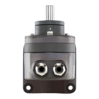
The electrical zero of the transmitter is marked on the end of the shaft and on the
outside of the casing (see Fig. 1):
- left for rotation transmitters with the range of 0 to 90º (-30%/+5%) or
0 to 140º (-30%/+5%)
Fig. 1
4. Electrical connections
The cable glands are provided for making the electrical connections to the transmitter.
Note that, ...
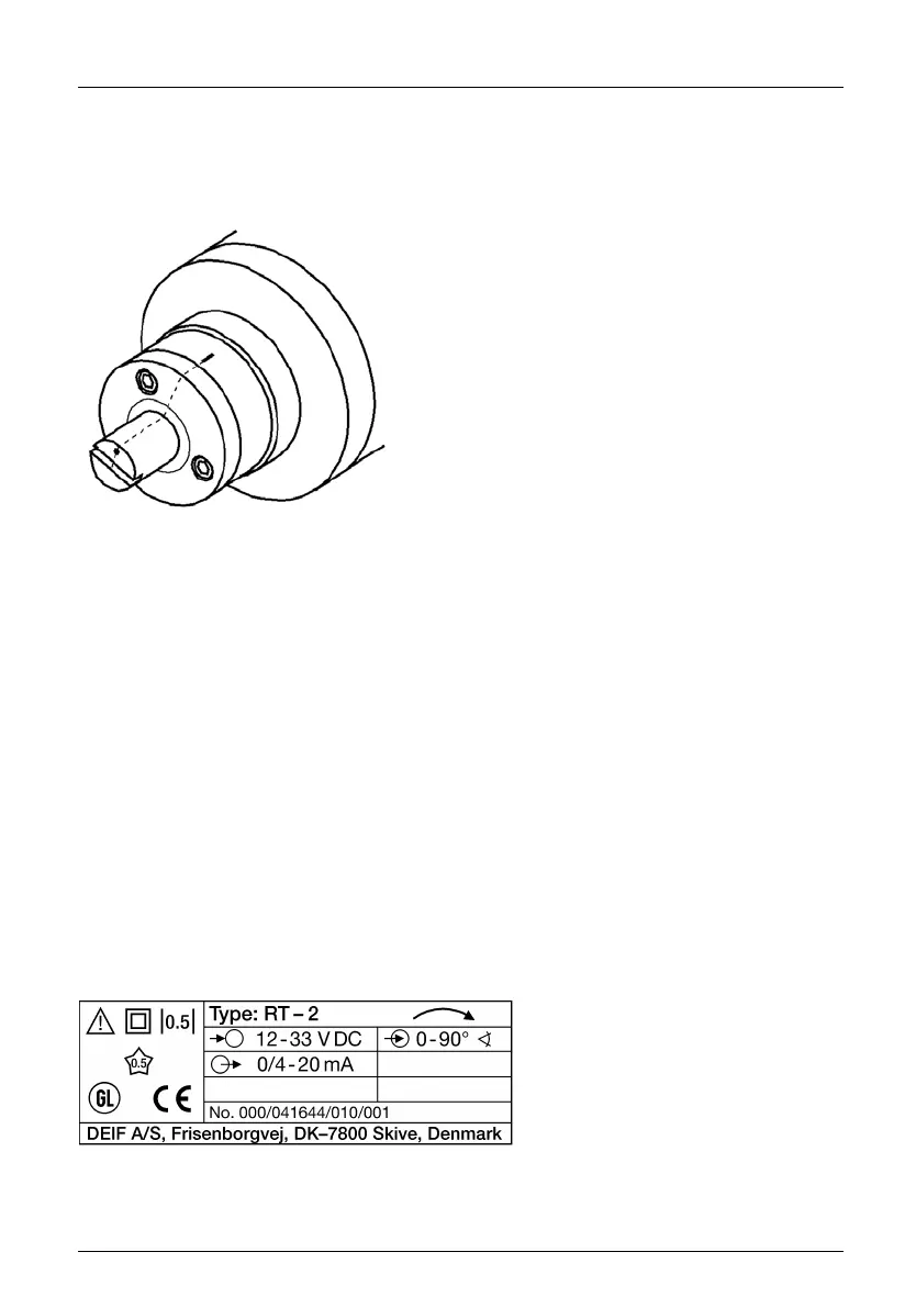
... the data required to carry out the prescribed measurement must correspond to
those marked on the nameplate (Fig. 2) of RT-2 (measuring input, measuring output,
power supply)!
... the total voltage drop do not exceed the supply voltage H[V], see “Measuring
output” a) in section 2 “Technical data” for maximum values of supply voltage H[V].
... the total loop resistance connected to the output (receiver plus leads) does not
exceed the maximum permissible value R
ext
! See “Measuring output” b) in Section 2
“Technical data” for the maximum values of R
ext
!
... twisted cores must be used for the measured variable input and output leads and
routed as far away as possible from power cables!
In all other respects, observe all local regulations when selecting the type of electrical
cable and installing them!
Fig. 2 Example of a nameplate.