Page 2 of 11 Tel.: (+45) 9614 9614 • Fax: (+45) 9614 9615 • E-mail: deif@deif.com
1. Brief description
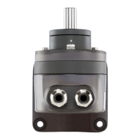
The RT-2 converts the position angle of a shaft into a load-independent direct current
signal, proportional to the angle position.
2. Technical data
Measuring input 0..90° or 0..140° (span adjustment –30/+5% of full scale)
Measuring output
Output variable I
A
: Load-independent DC current, proportional to the input
angle.
Standard ranges: 4...20mA, 2 wire connection or
0...20mA, 3 or 4-wire connection adjustable with
potentiometer
a) External voltage: (load voltage)
referring to DEIF illuminated instruments
(e.g. VTR-3, TRI-2 and others)
without electric isolation:
H[V]>[∑Load
inst
V+12V+(Loop
res
*I
A
)V]
Example:
System consists of 2 DLQ-ph, 1 VTR-3 and 1 TRI-2
voltage drop
DLQ-ph 0.6V x 2 = 1.2V
VTR-3 0.6V x 1 = 0.6V
TRI-2 3.0V x 1 = 3.0V
ΣLoad
inst
= 4.8V
Loop
res
: Cable resistance ≤ 200Ω
I
A
: System wired as 0...20mA.
This means I
A
= 20mA.
H[V] > 4.8V + 12V + 0.02A x 200Ω
⇓
H[V] > 20.8V DC
b) External resistance: (load resistance)
without electric isolation
R
ext.
max. [kΩ] = H[V] – 12V
I
A
[mA]
I
A
= Output signal end value
H[V] = Supply voltage (max. 33V DC)
Load
inst
= Voltage drop in the instrument
Load
res
= The total resistance of cable in the loop.
Accuracy
Reference value: Measuring range
Basic accuracy: Limit of error ≤ 0.5%