Page 4 of 11 Tel.: (+45) 9614 9614 • Fax: (+45) 9614 9615 • E-mail: deif@deif.com
3. Mounting
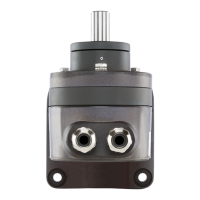
Transmitter
Drilling and cut-out diagrams for mounting transmitters
directly
...with a bracket
Table 1
The M6 screws are needed for the “directly” mounted version and four M8 nuts and
bolts for transmitter “with a bracket”. The screws, respectively nuts and bolts are not
supplied, because the required length varies according to the thickness of the
mounting surface.
When deciding where to install the transmitter (measuring location), take care that the
ambient conditions given in “Technical data” are not exceeded.
Make the cut-out or drill the holes in the item onto which the transmitter is to be
mounted according to the corresponding drilling and cut-out diagram given in Table 1
and then fit the transmitter.
Pay attention when aligning and tightening the transmitter that the electrical zero and
the zero of the item being measured coincide.
The holes in the mounting bracket are elongated for this purpose and permit the
transmitter to be rotated in order to adjust the electrical zero to coincide with the zero
of the measured device.
Similarly, it is advisable to elongate the three holes (6.5 mm diam.) drilled for “directly”
mounted version (see upper drilling and cut-out diagram in Table 1).