Page 8 of 11 Tel.: (+45) 9614 9614 • Fax: (+45) 9614 9615 • E-mail: deif@deif.com
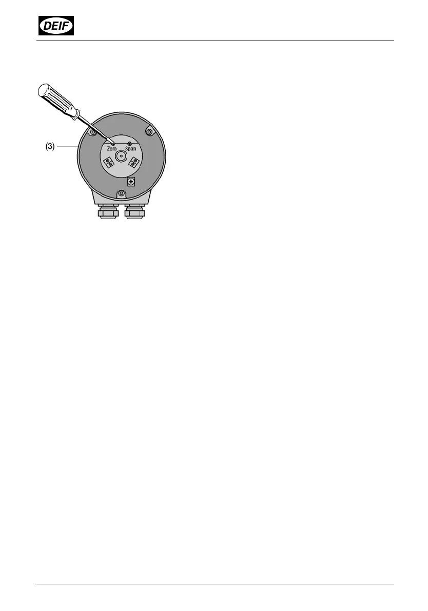
Then adjust the “ZERO” potentiometer (Fig. 5) using a watchmaker’s screwdriver (2.3
mm diam.) so that the desired output current flows.
Fig. 5 Rear of the transmitter with the adjustments “ZERO”, “SPAN”
Now rotate the measured device to its opposite limit position, i.e. the position at which
the RT-2 should produce 20 mA DC.
Adjust the “SPAN” potentiometer with the screwdriver as before until precisely the
prescribed full-scale output current is measured at the output.
Then recheck the zero point and correct on the ZERO potentiometer if necessary.
Check the full-scale value again. Repeat both adjustments until both zero point and
full-scale value are precise.
7. Adaptation from 2-wire connection to 3 or 4-wire connection
and vice versa
If, however, a transmitter be changed from one to the other (see wiring diagrams in
Fig. 4), the beginning and end of the measuring range must be readjusted.