Do you have a question about the Dekker Vmax and is the answer not in the manual?
General safety guidelines for operating and maintaining DEKKER products.
Instructions for storing the vacuum system in a cool, dry environment.
Guidelines for installing the vacuum system, including foundation and location.
Table detailing recommended wire and disconnect sizes for Vmax systems.
Correlates VFD percentage values with transducer voltage and vacuum levels.
Recommended wire and disconnect sizes for Vmax-VFD systems.
Instructions for installing inlet piping, including temporary screens and filter requirements.
Recommendations for discharge piping installation, including check valves and driplegs.
Information on cooling water supply requirements and temperature control valve operation.
A schematic diagram illustrating the vacuum pump system's components and flow.
Procedure for checking and ensuring proper alignment of drive couplings.
Verifying fluid levels, discharge pressure, and V-belt tension during startup.
Verifying motor voltage, current, and pump operating temperature.
How pumps operate when the selector is in HAND mode.
How pumps operate when the selector is in AUTO mode.
Details on automatic alternation and frequent stop/start protection.
Indicates pump overheating and causes shutdown.
Indicates low oil level, causing pump shutdown.
Lubrication requirements for pump bearings.
Schedule for lubricating pump bearings.
Guidelines for lubricating motor bearings.
Schedule for lubricating motor bearings.
Recommended hours or time periods for changing seal fluid.
Procedure for draining, filling, and bleeding air from the seal fluid system.
Initial checks after the first 8 hours of operation.
Routine checks every 500 hours.
Maintenance tasks required at 1000 hours.
Lubrication of bearings with grease fittings.
Using disconnect handles for system control.
Function of HOA selector switches.
Explains Power On, Pump Running, High Temp, etc. lights.
Operation of Audible Alarm, Alarm Silence, and Alarm Reset buttons.
Tracks operating hours for maintenance scheduling.
Devices to eliminate vibration transmission.
Valve to isolate the vacuum system.
Optional filter to prevent particles.
Protects pump from closed suction.
Automatically switches pumps ON/OFF based on demand.
Instructions for setting the controller's internal clock.
How the controller manages automatic mode operation.
Procedure to enter parameterization mode for changing settings.
How to navigate and select parameters within the controller.
Step-by-step guide to modify parameter values.
Guide for setting ON/OFF switch points for the controller.
Table correlating Vacuum (HgV) to PLC settings for controller configuration.
Standard switch points and block numbers for Simplex, Duplex, and Triplex systems.
Function of the high temperature switch and its shutdown mechanism.
Operation of the high back-pressure switch.
Function of the lag pump alarm.
Indicates transformer failure.
How the low oil level switch operates.
Protection against frequent stopping and starting.
Feature to equalize running time among pumps.
Troubleshooting steps for startup and shutdown issues.
Causes and solutions for unexpected system shutdowns.
Troubleshooting steps for systems not achieving desired vacuum levels.
Guidance on calling for service, parts, or system information.
Covers defects in material and workmanship.
Specific warranty terms for Vmax systems.
Outlines DEKKER's liability limitations.
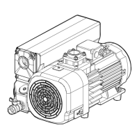
The DEKKER Vmax oil-sealed liquid ring vacuum pump system is designed to provide safe, reliable, and trouble-free service, offering advantages over other vacuum pump systems due to the absence of metal-to-metal contact between the impeller and casing. This design means the pump requires no internal lubrication. The system utilizes grease-lubricated bearings mounted externally to the pumping chamber, isolated by mechanical shaft seals. Operators must exercise good judgment and follow proper safety procedures during installation, start-up, and operation.
The Vmax system operates on the principle of a liquid ring vacuum pump, known for its simplicity and low maintenance requirements. The impeller assembly is the sole moving part, rotating freely within the casing without metal-to-metal contact. The sealing liquid creates a liquid piston action, generating vacuum and removing the heat of compression. This seal fluid circulates in a closed loop, passing through an air- or water-cooled heat exchanger that dissipates the heat. The discharge separator/reservoir holds the seal fluid and incorporates a high-efficiency separator arrangement to separate the seal fluid from the air or gases discharged by the pump.
For systems equipped with a Variable Frequency Drive (VFD) and an Operator Interface Module (OIM) remote keypad, the VFD controls the motor's RPM to maintain a desired vacuum level. In Manual Mode, the system runs at a constant RPM. In Auto Mode, the system monitors a set point configured by the operator via the OIM, adjusting the motor's RPM to achieve and maintain the target vacuum level. The OIM displays real-time data such as total run hours, Torr set point, Torr feedback, horsepower, AMPS, and Hertz.
The system includes various protective devices to prevent damage and aid in maintenance. A High Temperature Switch signals when the oil temperature exceeds a shut-down level, automatically shutting down the unit until the alarm is reset and the temperature drops. An optional High Back-pressure Switch indicates when the exhaust filter element needs replacement, signaling a pre-determined pressure level (e.g., 4 psi) in the separator discharge. An optional Low Oil Level Switch triggers a shut-down if the seal fluid level drops too low.
For multiplex systems, "Automatic alternation" ensures equal operating time among pumps by alternating the lead pump role. "Frequent stop/start protection" allows pumps to operate for a minimum duration (factory-set at 10 minutes) to prevent premature coupling failure and electrical component breakdown, even if the vacuum demand is met sooner.
Installation requires careful attention to location, mounting, and piping. The unit should be installed in a well-ventilated, dust-free area, at least 3 feet from surrounding walls for servicing. The foundation must be level, rigid, and substantial enough to absorb vibrations and support the total unit weight, with larger systems (over 40 HP) requiring grouting. Inlet piping should be at least the size of the pump inlet, with a temporary screen installed at start-up to protect against debris. A 10-micron inlet filter is recommended for dusty or particle-laden gases. A vacuum relief valve (anti-cavitation valve) is essential to prevent damage if the pump inlet becomes closed during operation. Discharge piping should be at least the size of the separator discharge, leading outside to prevent hazardous vapor accumulation.
For water-cooled systems, an adequate supply of cooling water (max 85°F, min 20 psig) is necessary. An optional automatic temperature control valve on the heat exchanger outlet regulates cooling water flow to maintain the system operating temperature between 140°F and 185°F.
Start-up procedures involve ensuring the seal fluid isolation valve is open, checking motor rotation (clockwise from the drive end), and verifying drive coupling alignment for non-monoblock units. For V-belt drives, proper belt tensioning is crucial to prevent premature wear and slipping. The seal fluid level in the separator reservoir must be at the FILL LINE on the sight gauge, with fluid added if necessary. After a brief run, the fluid level should be rechecked. Discharge pressure on the separator gauge should not exceed 2 psig under vacuum conditions, indicating proper discharge pipe system function.
Electrical preparation involves checking incoming voltage against system voltage and verifying proper motor rotation. If rotation is incorrect, two of the three main power leads on the contactor must be switched. All wiring must comply with OSHA, National Electric Code, and local codes, with a main disconnect switch recommended between the vacuum system and incoming power.
The system's operation can be managed via HAND-OFF-AUTO selector switches. In HAND mode, pumps start immediately and run continuously unless an alarm is triggered. In AUTO mode, pumps operate based on vacuum switches, which are typically set with a differential and offset for multiplex systems to ensure efficient operation and load sharing.
The Vmax system is designed for minimal maintenance, with service gauges alerting operators when attention is needed. Before any maintenance, all power must be disconnected from the system.
Bearing lubrication for the pump varies by model. Titan-series single-stage pumps (.25-20 HP) have sealed bearings requiring no field lubrication. Larger Titan-series pumps (25-100 HP) and two-stage pumps (2-60 HP) require lubrication every 3000 hours, with grease fittings located on top of each bearing housing. Maxima-K series pumps require lubrication every 1500 hours. Motors (where required) also have a lubrication schedule, typically every 6 months to 3 years depending on speed, frame size, and operating conditions, using high-temperature lithium-based grease.
Inlet filters (if installed) should be checked after the first 8 hours of operation and cleaned or replaced every 1000 to 3000 hours, or more frequently if excessive pressure drop is observed. Care must be taken to prevent foreign material from falling into the pump suction opening.
Seal fluid is crucial for performance and warranty. DEKKER Vmaxol seal fluid is recommended, with Standard Vmaxol requiring changes every 10,000 hours or annually, and Synthetic/Food grade Long-life Vmaxol every 15,000 hours or annually. Fluid changes involve draining the reservoir, pump, and heat exchanger at operating temperature, then refilling to the shaft centerline level. Overfilling the pump above the shaft centerline can cause damage. The seal fluid level should be checked every 500 hours for water build-up.
Devarnishing is recommended to maintain seal fluid quality. DEKKER offers Proclean 39V devarnishing compound for this purpose. Varnished pumps are not covered under warranty.
The seal fluid strainer should be cleaned after the first 50 hours of operation and then every 1000-3000 hours, or if excessive oil discharge temperature (above 185°F) indicates low oil flow.
Spin-on oil filters (if installed) should be changed if the operating temperature steadily increases. Separator elements, located in the separator reservoir, should be replaced every 10,000 hours or annually, or sooner if back-pressure exceeds 4 psig. The transparent oil return lines from the separator should be checked for blockage and replaced if necessary.
Mechanical shaft seals are fitted on all DEKKER pumps and do not require maintenance unless there is significant leakage (more than one drop per minute). Minor "weepage" (less than one drop per minute) is normal and not covered under warranty. Leakage due to abrasive particles or wear and tear is also not covered. Seal replacement instructions are model-specific and require factory consultation.
A comprehensive maintenance schedule includes:
| Capacity | Varies by model |
|---|---|
| Horsepower | Varies by model |
| Max Flow Rate | Varies by model |
| Max Head | Varies by model |
| Power | Electric |
| Voltage | Varies by model |
| Frequency | 50/60 Hz |
| Inlet/Outlet Size | Varies by model |
| Weight | Varies by model |