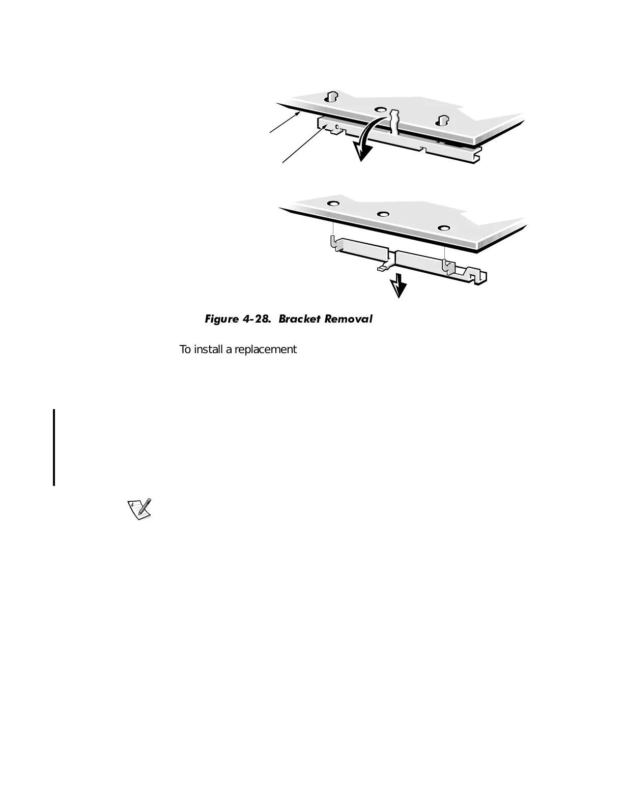
Removing and Replacing Parts 4-29
10. Remove the mounting bracket from the back of the system board (see
Figure 4-28).
)LJXUH %UDFNHW 5HPRYDO
To install a replacement system board, install the guide bracket assembly
for the SEPP or SEC cartridge. The assembly is keyed for correct insertion (see
Figure 4-25). Then install the microprocessor and heat sink assembly. Transfer
the DIMMs to the new system board.
When installing a replacement system board, angle the back of the board
downward and carefully align the connectors on the back edge of the board
with the cutouts in the I/O gasket (see Figure 4-24). When properly aligned,
the board connectors slide into the I/O gasket as you lower the board into
position in the chassis and reseat it on the three plastic standoffs. Then replace
the system-board mounting screw.
NOTE: The system-board mounting screw pulls the system board against the
I/O gasket to prevent EMI leakage.
After installing the replacement system board, replace the expansion cards
that you removed from the old system board.
When reconnecting the cables to a system board with integrated sound, be
sure to connect the CD-ROM drive audio cable to the connector nearest the
back edge of the system board. The middle audio connector is used with a
modem.
To configure the system after installing a replacement board, follow these
steps:
1. Install the jumper plug on pins 2 and 3 of configuration jumper J9D3 (see
Figure 4-27) to select Maintenance mode.
system board
system-board
mounting bracket
1.
2.