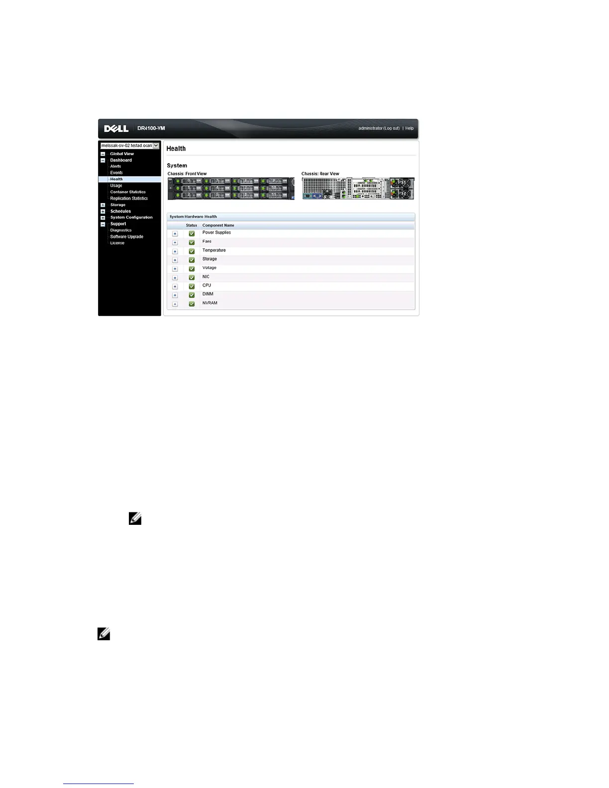
Health Page: DR4100 System
Figure 2 Health Page (DR4100 System and Components)
DR Series System Components
In the System tab on the Health page, the following images and System Hardware Health table display the status of the
system components (for specific locations, see the Figures).
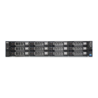
• Chassis: front view (image)—shows the 0 -11 drive locations and status
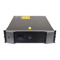
• Chassis rear view (image)—shows power supply locations and status, and positions of rear panel connectors
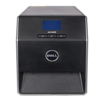
• OS internal drives (image)—shows the status for the operating system internal drives
• System Hardware Health (table)—shows the current status for all of the major hardware subcomponents in the
appliance:
– Power Supplies—status, name, and location
– Fans—status, name, speed, and identifier
– Temperature—status, name, and temperature
– Storage—storage controller, storage virtual disks, storage physical disks, storage controller battery, and
storage cache
NOTE: The storage controller battery state displays either as
Ready
or
Charging
(the latter indicates this
state after a system reboot until the storage controller battery is fully charged).
– Voltage—status, name, voltage, and probe name
– NIC (network interface card)—status, name, type, and speed
– CPU (central processing unit)—status and name
– DIMM (dual in-line memory module)—status, name, and connector name
– NVRAM (non-volatile random access memory)—NVRAM (status, name, errors, temperature, SSD state, SSD
health, SSD firmware version, serial number, and firmware version); NVRAM super capacitor (status, name,
state, voltage, and maximum design voltage)
NOTE: To display the current status, name, and state of chassis components, hover your mouse over the
component.
All system hardware components are listed in the System Hardware Health pane by component name, status, and other
attributes. The following table identifies the component status by one of three color-coded icons that reflect its state.
49
 Loading...