Icon Description
This color code icon indicates that the component status is operating at an optimal state.
This color code icon indicates that the component status is a operating under a warning state (a
non-critical error has been detected).
This color code icon indicates that the component status is operating under an error or
actionable state (a critical error has been detected).
To expand any component category to display more status details for each related subcomponent, click + ("plus sign"
icon) in the System Hardware Health pane. To contract any expanded component category, click — ("minus sign" icon).
For more information, see Monitoring System Health.
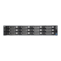
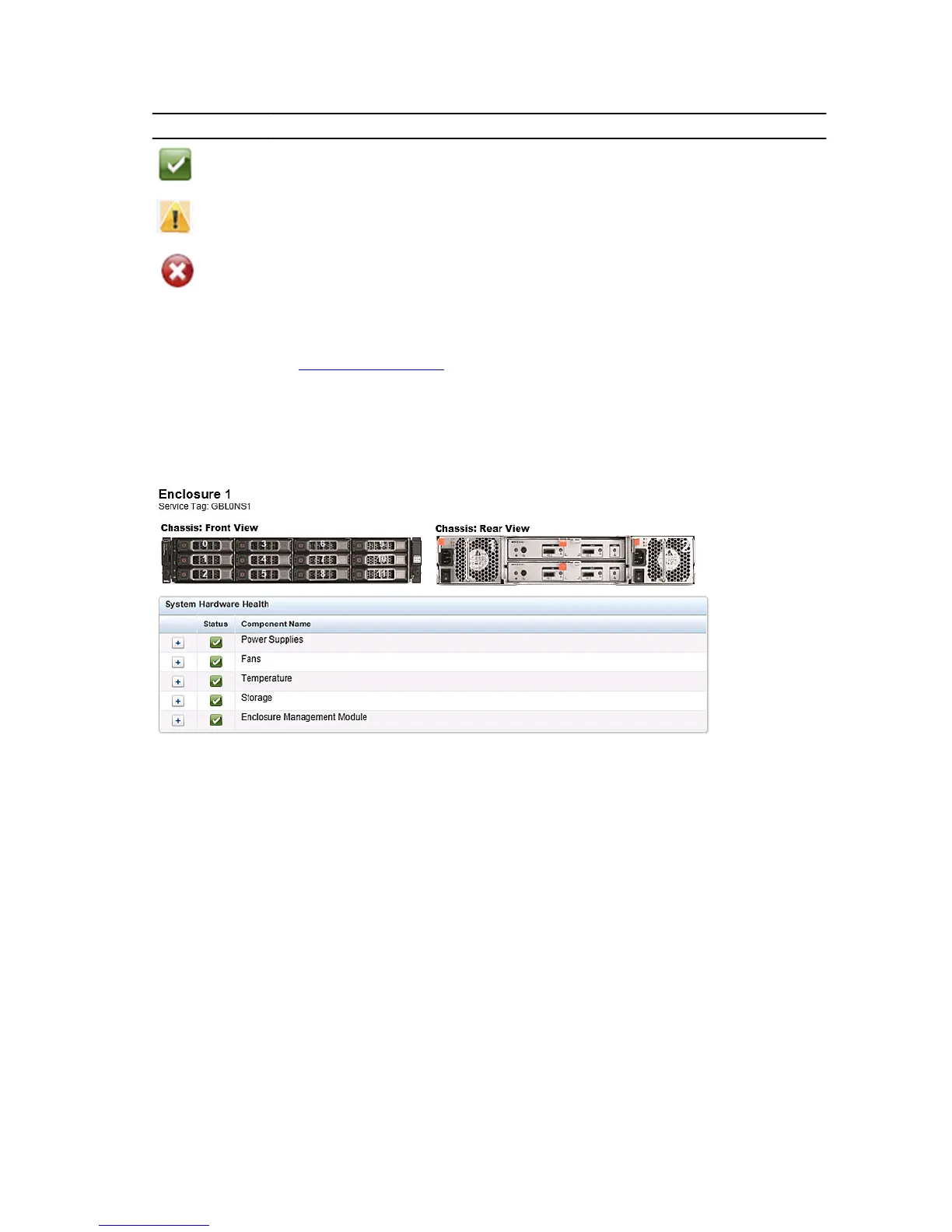
DR Series System Enclosures
In the Enclosure tab on the Health page, the following images and System Hardware Health table display the status of
the expansion shelf enclosure components (for specific locations, see Figure 4).
Figure 4 Expansion Shelf Components
• Chassis: front view (image)—shows the 1 -11 drive locations and status; drive 0 is the dedicated hot spare for RAID 6
• Chassis rear view (image)—shows cooling fan locations and status, and positions of rear panel connectors
• Service Tag—lists the service tag for the selected expansion shelf
• System Hardware Health (table)—shows the current status for all of the major hardware subcomponents in the
expansion shelf:
– Power Supplies—status, name, and location
– Fans—status, name, speed, and identifier
– Temperature—status, name, and temperature
– Storage—storage physical disks (status, slot, serial number, state, GHS status, spare state, smart alert, and size)
– Enclosure Management Module (status, name, identifier, and Nexus ID)
50
 Loading...