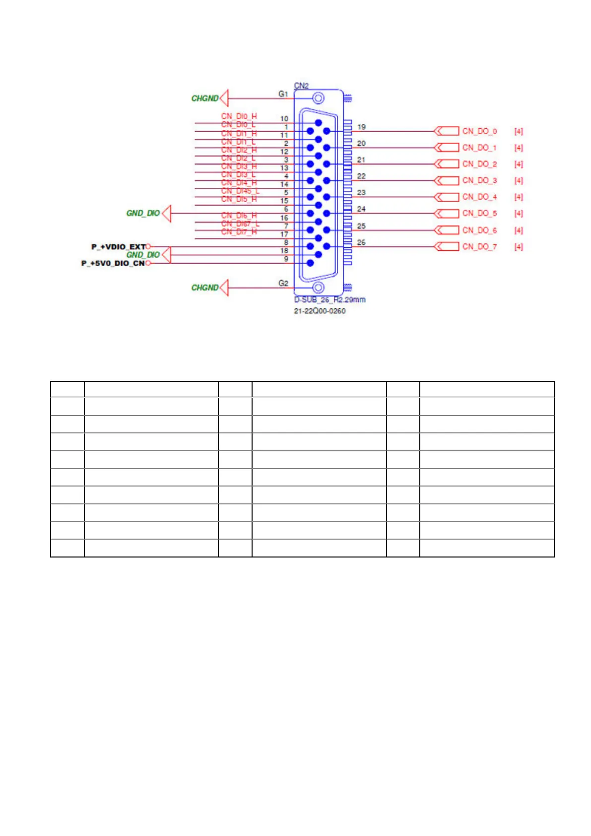
Figure 106. DI/O connector pin locations
Table 12. DI/O connector pin definitions
Pin Signal Pin Signal Pin Signal
1 DI0_L 10 DI0_H 19 DO0
2 DI1_L 11 DI1_H 20 DO1
3 DI2_L 12 DI2_H 21 DO2
4 DI3_L 13 DI3_H 22 DO3
5 DI4_L/DI5_L 14 DI4_H 23 DO4
6 GND_DIO 15 DI5_H 24 DO5
7 DI6_L/DI7_L 16 DI6_H 25 DO6
8 +VDIO_EXT 17 DI7_H 26 DO7
9 +5V0_DIO 18 GND_DIO - -
10. Use the screws to reattach the bottom panel. See the screw locations in step 1.
Installation procedure for 8x DI/O uFM module
59

 Loading...