Table 1. Expansion module packing list - 4G (continued)
Item Quantity Notes
4G label 1 -
4G heat sink 1 -
Thermal pad 1 -
Table 2. Expansion module packing list - 5G
Item Quantity Notes
Screw M3 x 6L 1 Torque required: 4.0 kgf.cm
Screw M3 x 4L 7 Torque required: 4.0 kgf.cm
Standoff H7.8 1 Torque required: 4.5 kgf.cm
Standoff H19.5 2 Torque required: 4.5 kgf.cm
Bracket 1 -
5G M.2 1 -
SMA cable 4 -
Antenna 4 -
5G label 1 -
5G heat sink 1 -
Thermal pad 1 -
Steps
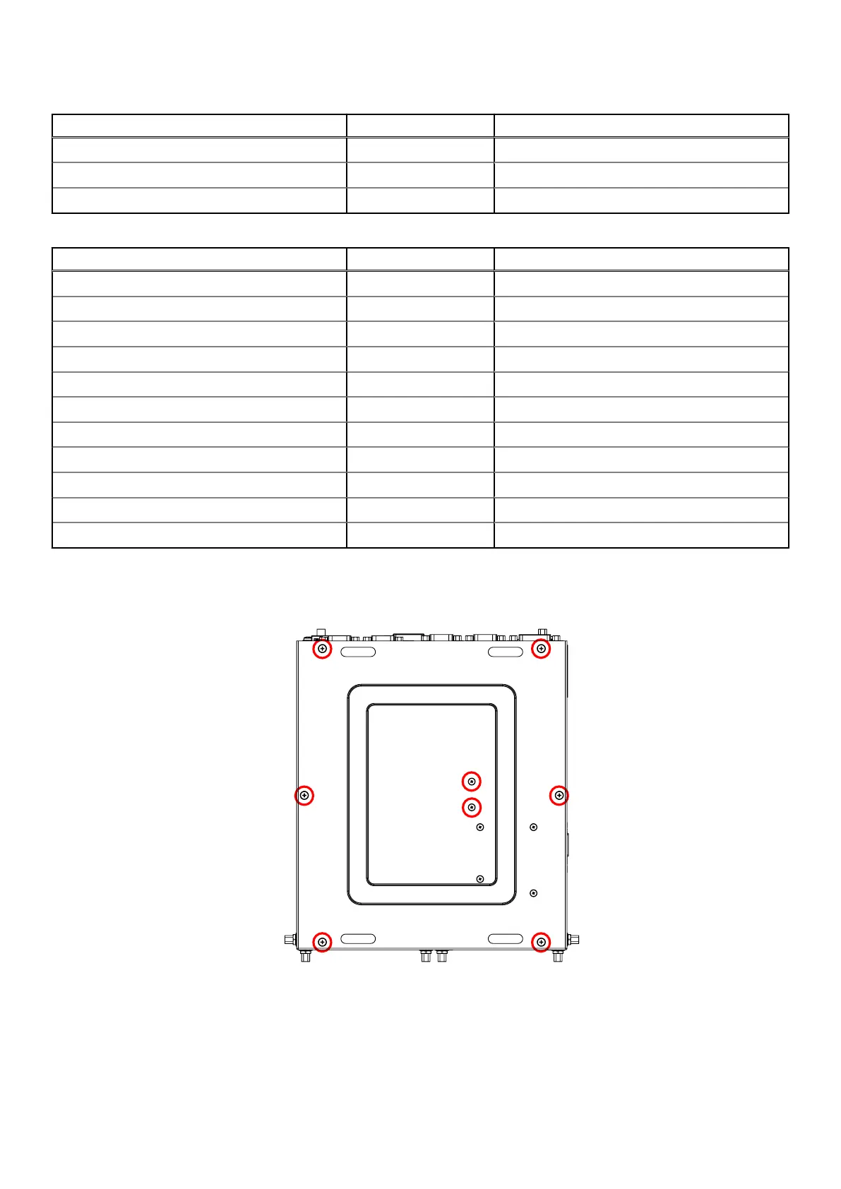
1. Remove the eight screws from the bottom panel of the EGW-5200, as shown in the following figure, and remove the bottom
panel.
Figure 6. Bottom panel screw locations
2. Remove the screws and nuts from the inside of the bottom panel and side panel, as shown in the following figures.
8
Installation procedure for 4G and 5G expansion modules
 Loading...