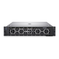
Figure 33. Installing a drive into the drive carrier
Next steps
1. Install the drive carrier.
Cable routing
Figure 34. Cable routing - 4 x 3.5-inch backplane configuration with PERC adapter
Table 11. Cable routing - 4 x 3.5-inch backplane configuration with PERC adapter
From To
BP_PWR_1 (Power connector on backplane) HDD/ODD_PWR (PIB connector on the system board)
CTRL_SRC_SA1 (Signal connector on the PERC) BP_DST_SA1 (Signal connector on backplane)
Installing and removing system components 43

 Loading...
