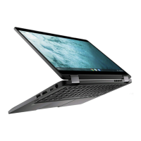
About this task
The following image indicates the connectors on your system board.
Figure 1. System-board connectors
1. Fan cable connector 2. Display cable connector
3. DC-in port connector 4. WLAN card connector
5. Touchpad cable connector 6. Battery cable connector
7. M.2 solid-state drive connector 8. I/O board cable connector
9. Speaker cable connector
The following images indicate the location of the system board and provide a visual representation of the removal procedure.
50
Removing and installing components
 Loading...