Steps
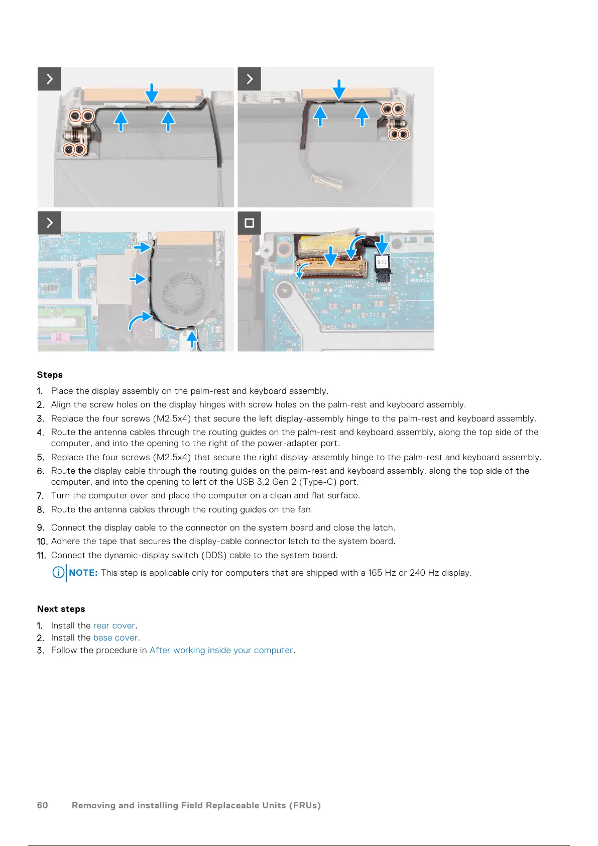
1. Place the display assembly on the palm-rest and keyboard assembly.
2. Align the screw holes on the display hinges with screw holes on the palm-rest and keyboard assembly.
3. Replace the four screws (M2.5x4) that secure the left display-assembly hinge to the palm-rest and keyboard assembly.
4. Route the antenna cables through the routing guides on the palm-rest and keyboard assembly, along the top side of the
computer, and into the opening to the right of the power-adapter port.
5. Replace the four screws (M2.5x4) that secure the right display-assembly hinge to the palm-rest and keyboard assembly.
6. Route the display cable through the routing guides on the palm-rest and keyboard assembly, along the top side of the
computer, and into the opening to left of the USB 3.2 Gen 2 (Type-C) port.
7. Turn the computer over and place the computer on a clean and flat surface.
8. Route the antenna cables through the routing guides on the fan.
9. Connect the display cable to the connector on the system board and close the latch.
10. Adhere the tape that secures the display-cable connector latch to the system board.
11. Connect the dynamic-display switch (DDS) cable to the system board.
NOTE: This step is applicable only for computers that are shipped with a 165 Hz or 240 Hz display.
Next steps
1. Install the rear cover.
2. Install the base cover.
3. Follow the procedure in After working inside your computer.
60
Removing and installing Field Replaceable Units (FRUs)
61 / 111 60 / 109 61 / 111
 Loading...