Steps
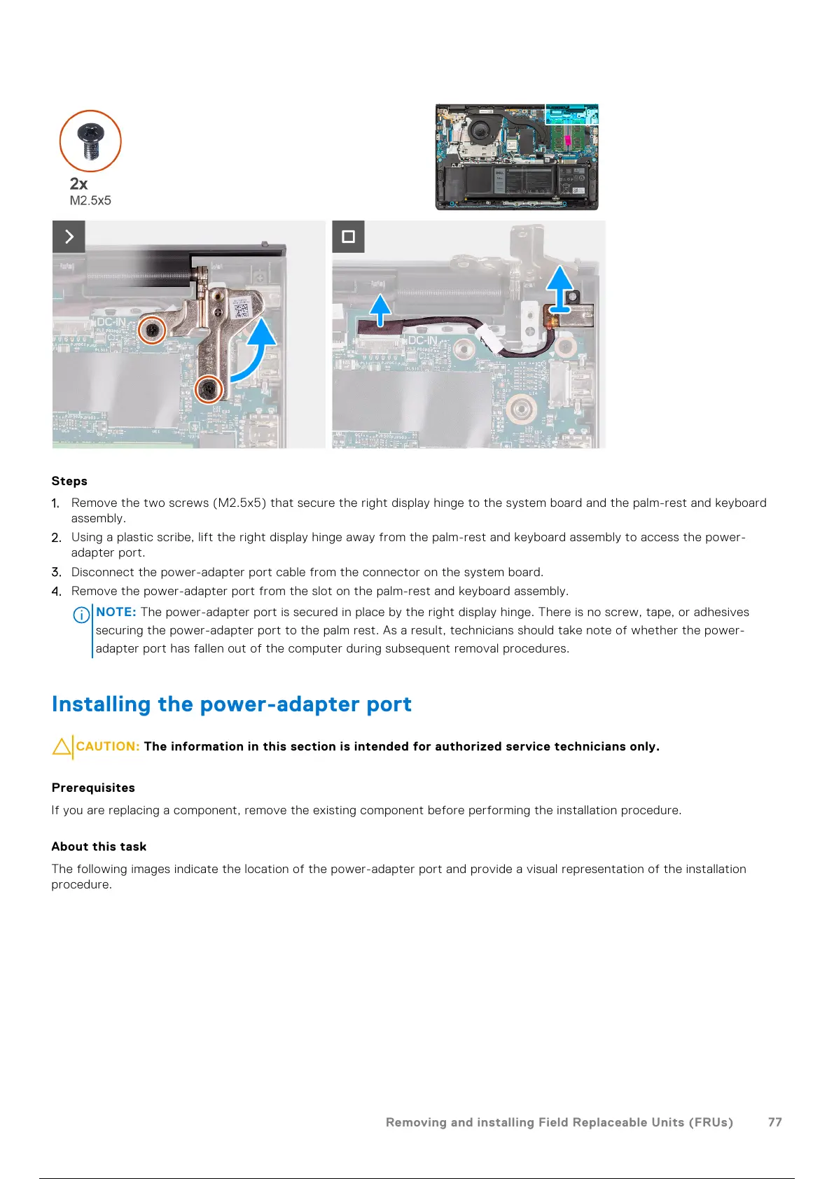
1. Remove the two screws (M2.5x5) that secure the right display hinge to the system board and the palm-rest and keyboard
assembly.
2. Using a plastic scribe, lift the right display hinge away from the palm-rest and keyboard assembly to access the power-
adapter port.
3. Disconnect the power-adapter port cable from the connector on the system board.
4. Remove the power-adapter port from the slot on the palm-rest and keyboard assembly.
NOTE:
The power-adapter port is secured in place by the right display hinge. There is no screw, tape, or adhesives
securing the power-adapter port to the palm rest. As a result, technicians should take note of whether the power-
adapter port has fallen out of the computer during subsequent removal procedures.
Installing the power-adapter port
CAUTION: The information in this section is intended for authorized service technicians only.
Prerequisites
If you are replacing a component, remove the existing component before performing the installation procedure.
About this task
The following images indicate the location of the power-adapter port and provide a visual representation of the installation
procedure.
Removing and installing Field Replaceable Units (FRUs)
77
78 / 136