g 2.5–inch drive assembly
h heat sink
i bezel
j cover
7 Follow the procedure in After working inside your computer.
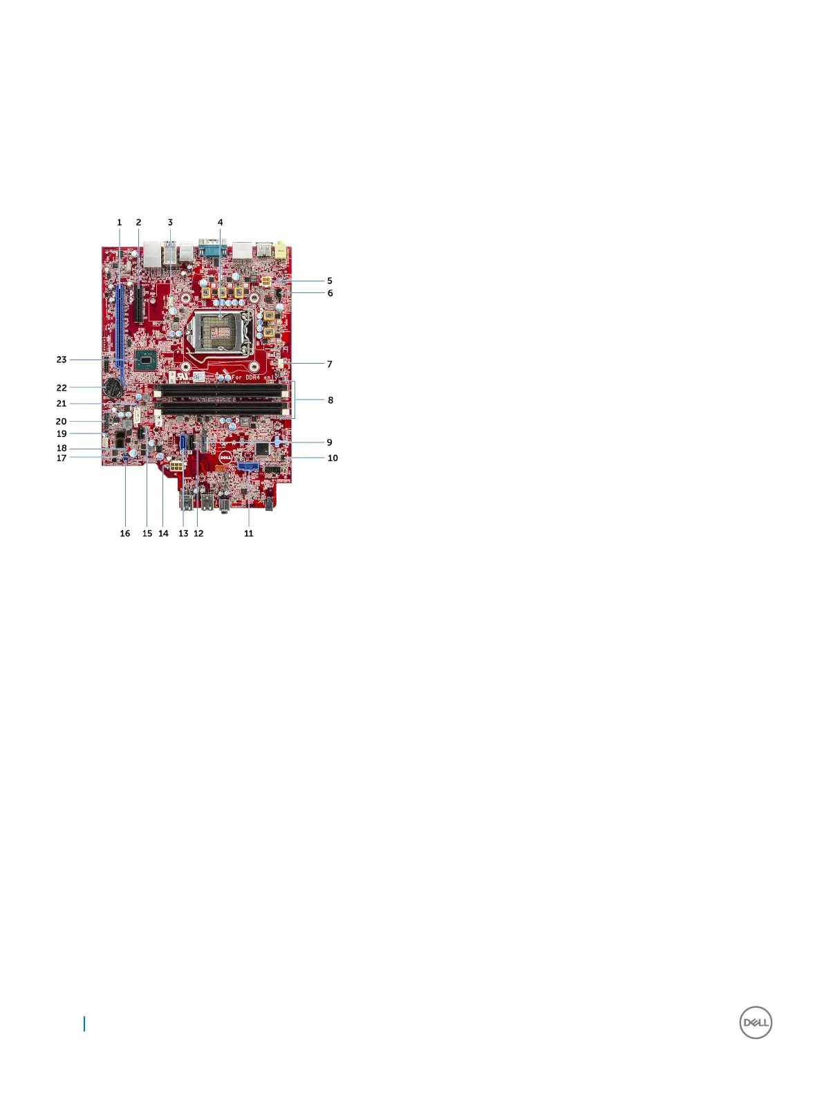
System board layout
1 PCI-e x16 Connector (slot 2) 2 PCI-e x4 Connector (slot 1) – open ended x4 to support x16
3 VGA Daughter Board Connector (VGA) 4 Processer Socket (CPU)
5 CPU Power Connector (ATX_CPU) 6 Intrusion Switch Connector (INTRUDER)
7 CPU Fan Connector (FAN_CPU) 8 Memory Slots (DIMM1, DIMM2, DIMM3, DIMM4)
9 M.2 Slot 3 Connector (M.2_SSD) 10 Power Switch Connector (PWR_SW)
11 Media Card Reader Connector (CARD_READER) 12 SATA2 Connector Black Color (SATA2)
13 SATA0 Connector Blue Color (SATA0) 14 ATX Power Connector (ATX_SYS)
15 HDD and ODD Power Cable Connector (SATA_PWR) 16 Service Mode jumper (SERVICE_MODE)
17 Clear Password Jumper (PASSWORD_CLR) 18 Clear CMOS Jumper (CMOS_CLR)
19 Internal Speaker Connector (INT_SPKR) 20 Internal USB Connector (WF_BT_USB)
21 SATA1 Connector White Color (SATA 1)
22 Battery Connector (BATTERY)
23 PCH Chipset
34 Removing and installing components