Do you have a question about the Dell OptiPlex XE2 and is the answer not in the manual?
Essential safety precautions and preparatory steps before performing any internal computer maintenance.
Detailed instructions on how to properly shut down the computer's operating system and power off the system.
Steps to reconnect external devices, cables, and power after completing internal computer maintenance.
Lists the essential tools required for performing component removal and installation procedures.
Step-by-step guide to safely remove the computer's chassis cover.
Instructions for correctly reattaching the computer's chassis cover after component replacement.
Procedure for disconnecting and removing the chassis intrusion switch.
Procedure for connecting and installing the chassis intrusion switch.
Guide to disconnecting the antenna and removing the WLAN card from its slot.
Steps to insert the WLAN card, secure it, and reconnect the antenna.
Instructions for releasing retention clips and removing the front bezel from the computer chassis.
Procedure to align and secure the front bezel back onto the computer chassis.
Steps to disconnect cables and release latches for removing expansion cards.
Procedure for inserting expansion cards into slots and securing them.
General guidelines for optimal performance when configuring system memory modules.
Instructions for releasing retaining tabs and removing memory modules from sockets.
Steps to align, insert, and secure memory modules into the system board connectors.
Guide to releasing the battery latch and removing the coin-cell battery from the system board.
Procedure to place and secure the coin-cell battery into its system board slot.
Steps to disconnect cables, release securing tabs, and remove the hard drive bracket.
Procedure to insert the hard drive into its bracket and bay, reconnect cables.
Steps to unlock the optical drive latch and slide it out of the computer.
Procedure to insert the optical drive and secure it using the drive latch.
Instructions for disconnecting the speaker cable and removing the speaker assembly.
Steps to slide the speaker into its slot and connect its cable to the system board.
Guide to disconnecting power cables and removing screws to take out the power supply unit.
Steps to place, secure, and connect the power supply unit and its cables.
Procedure to disconnect the fan cable and loosen captive screws to remove the heat sink.
Steps to place, secure, and connect the heat sink assembly and its fan cable.
Guide to releasing the lever, removing the processor cover, and extracting the processor.
Procedure to insert the processor, lower the cover, and secure the retention lever.
Instructions for disconnecting the fan cable and removing the fan from its grommets.
Steps to place the fan, pass grommets, and connect the fan cable.
Guide to disconnecting the sensor cable and releasing tabs to remove the thermal sensor.
Procedure to secure the thermal sensor, thread its cable, and connect it to the system board.
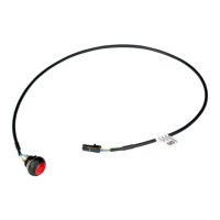
Instructions for disconnecting the power switch cable and releasing clips to remove the switch.
Steps to slide the power switch in, secure its cable, and connect it to the system board.
Guide to disconnecting I/O cables and removing screws to detach the I/O panel.
Procedure to insert the I/O panel, secure it with screws, and connect its cables.
Steps to disconnect cables, remove screws, and tilt the system board out of the chassis.
Procedure to align, place, secure the system board, and reconnect cables.
Diagram and list identifying various components and connectors on the system board.
Configures the order in which the computer attempts to find and load an operating system.
Details the keyboard keys used for navigating and interacting within the System Setup utility.
Describes various configuration settings available within the System Setup, such as System Information and Boot Sequence.
Provides instructions for downloading and installing BIOS updates from the Dell support website.
Explains the function and location of system board jumpers, including the password jumper.
Instructions for setting, changing, and disabling system and setup passwords for security.
Guide to running the embedded system diagnostics to test computer hardware for issues.
Interprets the diagnostic codes indicated by the power button LED's color and blinking patterns.
Explains the system's beep codes that identify hardware problems during startup.
Lists common error messages and their descriptions, aiding in problem diagnosis.
| Tcase | 71.35 °C |
|---|---|
| Bus type | QPI |
| Stepping | C0 |
| Tjunction | - °C |
| FSB Parity | No |
| Processor cache | 6 MB |
| Processor cores | 4 |
| System bus rate | - GT/s |
| Processor family | Intel® Core™ i5 |
| Processor series | Intel Core i5-4500 Desktop Series |
| Processor socket | LGA 1150 (Socket H3) |
| Processor codename | Haswell |
| Number of QPI links | 1 |
| Processor frequency | 2.9 GHz |
| Processor cache type | Smart Cache |
| Configurable TDP-down | - W |
| Processor lithography | 22 nm |
| Processor manufacturer | Intel |
| Processor front side bus | - MHz |
| PCI Express slots version | 3.0 |
| Processor boost frequency | 3.6 GHz |
| Processor operating modes | 64-bit |
| PCI Express configurations | 1x16, 2x8, 1x8+2x4 |
| Thermal Design Power (TDP) | 65 W |
| Maximum number of PCI Express lanes | 16 |
| Memory types supported by processor | DDR3-SDRAM |
| Memory voltage supported by processor | 1.5 V |
| Memory clock speeds supported by processor | 1333, 1600 MHz |
| Memory bandwidth supported by processor (max) | 25.6 GB/s |
| Maximum internal memory supported by processor | 32 GB |
| On-board graphics card ID | 0x412 |
| Discrete graphics card model | Not available |
| On-board graphics card model | Intel® HD Graphics 4600 |
| Graphics card Open GL support | Yes |
| On-board graphics card family | Intel® HD Graphics |
| Maximum on-board graphics card memory | 1.74 GB |
| On-board graphics card OpenGL version | 4.3 |
| On-board graphics card base frequency | 350 MHz |
| On-board graphics card DirectX version | 11.1 |
| On-board graphics card dynamic frequency (max) | 1150 MHz |
| Number of displays supported (on-board graphics) | 3 |
| Scalability | 1S |
| Processor code | SR14J |
| Processor ARK ID | 75044 |
| Intel TSX-NI version | 0.00 |
| Processor package size | 37.5 x 37.5 mm |
| Supported instruction sets | AVX 2.0, SSE4.1, SSE4.2 |
| Thermal solution specification | PCG 2013C |
| Intel Identity Protection Technology version | 1.00 |
| Intel® Matrix Storage Technology (Intel® MST) | - |
| Memory slots | 4x DIMM |
| Internal memory | 4 GB |
| Memory channels | Dual-channel |
| Memory clock speed | 1600 MHz |
| Memory layout (slots x size) | 2 x 2 GB |
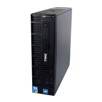
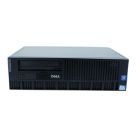
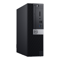
| Chassis type | SFF |
| Product color | Black |
| Placement supported | Vertical |
| Product type | PC |
| Motherboard chipset | Intel® Q87 |
| Password protection type | BIOS, User |
| HDD size | 3.5 \ |
| HDD speed | 7200 RPM |
| HDD interface | SATA |
| Storage media | HDD |
| Optical drive type | DVD-ROM |
| Total storage capacity | 500 GB |
| Cabling technology | 10/100/1000Base-T(X) |
| Ethernet LAN data rates | 10, 100, 1000 Mbit/s |
| USB 2.0 ports quantity | 6 |
| USB 3.2 Gen 2 (3.1 Gen 2) Type-A ports quantity | 0 |
| Power supply | 315 W |
| Operating altitude | -15.2 - 3048 m |
| Non-operating altitude | -15.2 - 10668 m |
| Storage temperature (T-T) | -40 - 65 °C |
| Operating temperature (T-T) | 5 - 35 °C |
| Storage relative humidity (H-H) | 5 - 95 % |
| Operating relative humidity (H-H) | 20 - 80 % |
| Sustainability certificates | RoHS, ENERGY STAR |
| Cables included | AC |
| Depth | 312 mm |
|---|---|
| Width | 93 mm |
| Height | 290 mm |
| Weight | 6000 g |