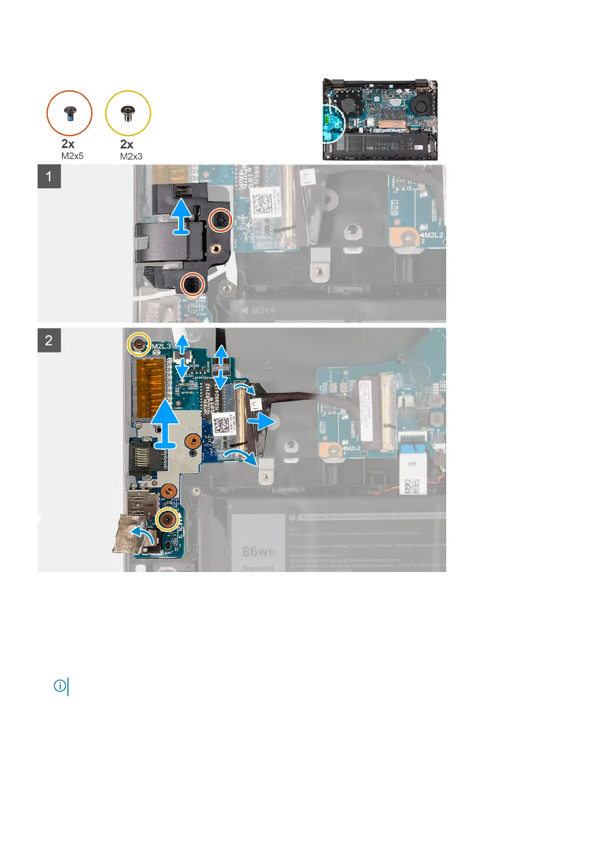
Steps
1. Remove the two screws (M2x5) that secure the RJ45 network-port assembly to the I/O board.
2. Lift the RJ45 network-port assembly off the I/O board.
3. Peel the tape that secures the I/O-board cable connector latch to the I/O board.
4. Open the latch and disconnect the power-button board cable from the I/O board.
5. Open the latch and disconnect the fingerprint-reader cable from the I/O board.
NOTE: This step is only applicable to computers shipped with a fingerprint reader.
6. Peel the Mylar that covers the I/O board.
7. Remove the two screws (M2x3) that secure the I/O board to the palm-rest and keyboard assembly.
8. Lift the I/O board off the palm-rest and keyboard assembly.
Removing and installing components
43