7. Speaker (woofers) cable connector
8. Touchpad-cable connector
9. I/O board-cable connector
10. Left fan cable connector
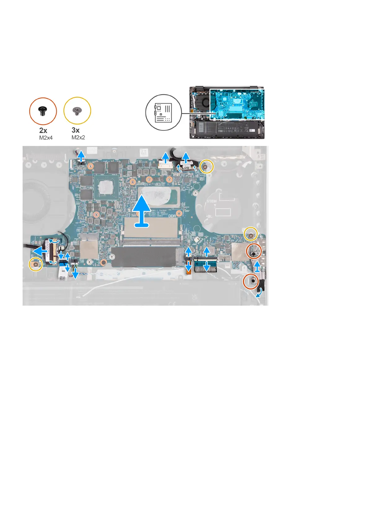
The following image(s) indicate the location of the system board and provides a visual representation of the removal procedure.
Steps
1. Disconnect the speaker (tweeter) cable from the system board.
2. Peel off the adhesive tape that secures the power-adapter port cable to the system board.
3. Disconnect the power-adapter port cable from the system board.
4. Peel the clear adhesive tape off the display-cable connector.
5. Open the latch and disconnect the display cable from the system board.
6. Remove the two screws (M2x4) that secure the Type-C port bracket to the system board.
7. Lift the Type-C port-bracket off the system board.
8. Open the latch and disconnect the keyboard cable from the system board.
9. Open the latch and disconnect the keyboard-backlight cable from the system board.
10. Peel the Mylar off the speaker (woofer) cable.
11. Disconnect the speaker (woofer) cable from the system board.
12. Disconnect the fan cable from the system board.
13. Open the latch and disconnect the touchpad cable from the system board.
14. Peel the clear adhesive tape off the I/O board connector.
15. Disconnect the I/O board cable from the system board.
16. Remove the three screws (M2x2) that secure the system board to the palm-rest and keyboard assembly.
17. Lift the system board at angle off the palm-rest and keyboard assembly, to clear the ports from the port openings.
Removing and installing components
57