5. Remove the wireless card
6. Remove the heat sink.
7. Remove the left fan.
8. Remove the right fan.
About this task
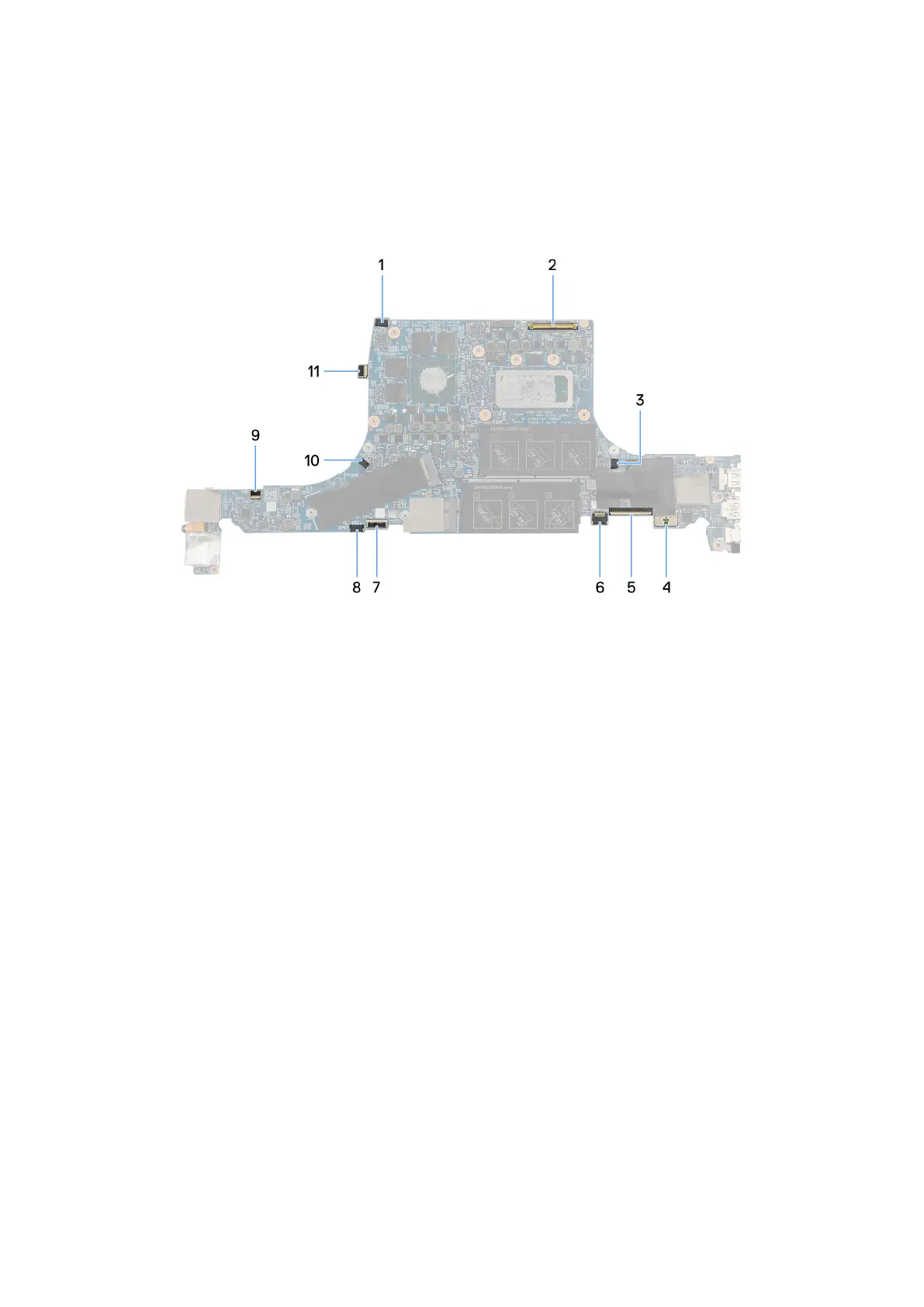
The following image indicates the connectors on your system board.
Figure 5. System board (front)
1. Speaker (tweeters) cable connector
2. Display cable connector
3. Right-fan cable connector
4. Battery cable connector
5. Keyboard cable connector
6. Keyboard-backlight cable connector
7. Touchpad-cable connector
8. Speakers (woofers) cable connector
9. Power button board cable connector
10. Left-fan cable connector
11. Fingerprint-reader cable connector
72
Removing and installing Field Replaceable Units (FRUs)