About this task
The following image indicates the connectors on your system board.
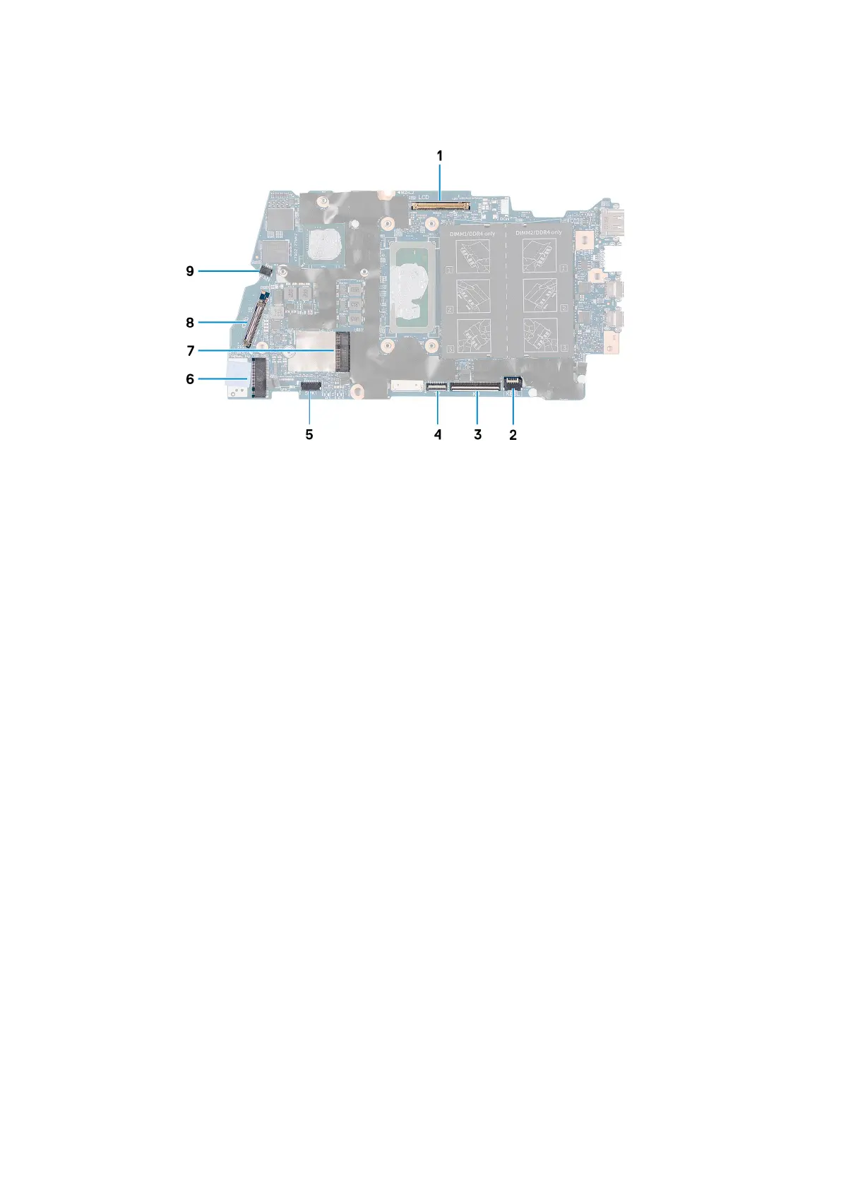
Figure 1. System-board connectors
1.
Display cable 2. Keyboard-backlight cable
3. Keyboard cable 4. Touchpad cable
5. Speaker cable 6. M.2 card slot for solid-state drive
7. M.2 card slot for wireless card 8. I/O-board cable
9. Fan cable
The following image indicates the location of the system board and provides a visual representation of the removal procedure.
50
Removing and installing components