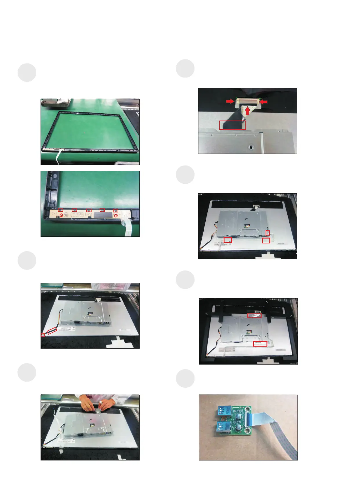
4. Disassembly and Assembly Procedures
S10
Put the panel module with the bracket into the front
bezel carefully to avoid pressing the function key
cable, then adjust position of the bracket chassis
module till the both parts firmly attached.
Push the earing-lock, connect LVDS cable to the
connector of panel module, then fix the cable with
the double-faced tape which sticked on the back of
the cable.
S11
S12
Use a proper tool to connect the function key cable
to the connector of the board. Fix the function key
cable by two adhesive tapes which taped on the
back of the cable as the positions of No.1 2.~
Connect the panel power cable to the connector of
the panel module, then tear off the adhesive tape
which sticked on the back of cable, fix the cable to
the panel.
1
2
Use a Jip to fix the bracket chassis base module and
panel module, then stick two pieces of aluminium foil
to fix the bracket chassis base on the positions of
the panel as the picture below shown.
aluminum foil
S13
S8
S9
aluminum foil
Take a function key board and a front bezel, then
locate the function keyboard into the hooks of the
front bezel for the two parts firmly attached as the
picture below shown. Put the front bezel on a protect
cushion for later assembling.
Take a USB board, a USB hub and a connect cable.
Connect the cable to the USB board, then locate the
USB board into the USB hub.
S14