148 Installing System Components
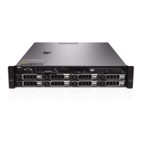
Figure 3-30. Removing and Installing the Control Panel—LED (Four–Hard-Drive System)
1 control panel cable 2 USB memory key connector
3 power cable 4 standoff
5 LED display module 6 slot
7 control panel board 8 mounting screws (2)
book.book Page 148 Friday, November 20, 2009 2:56 PM

 Loading...