Installing System Components 153
6
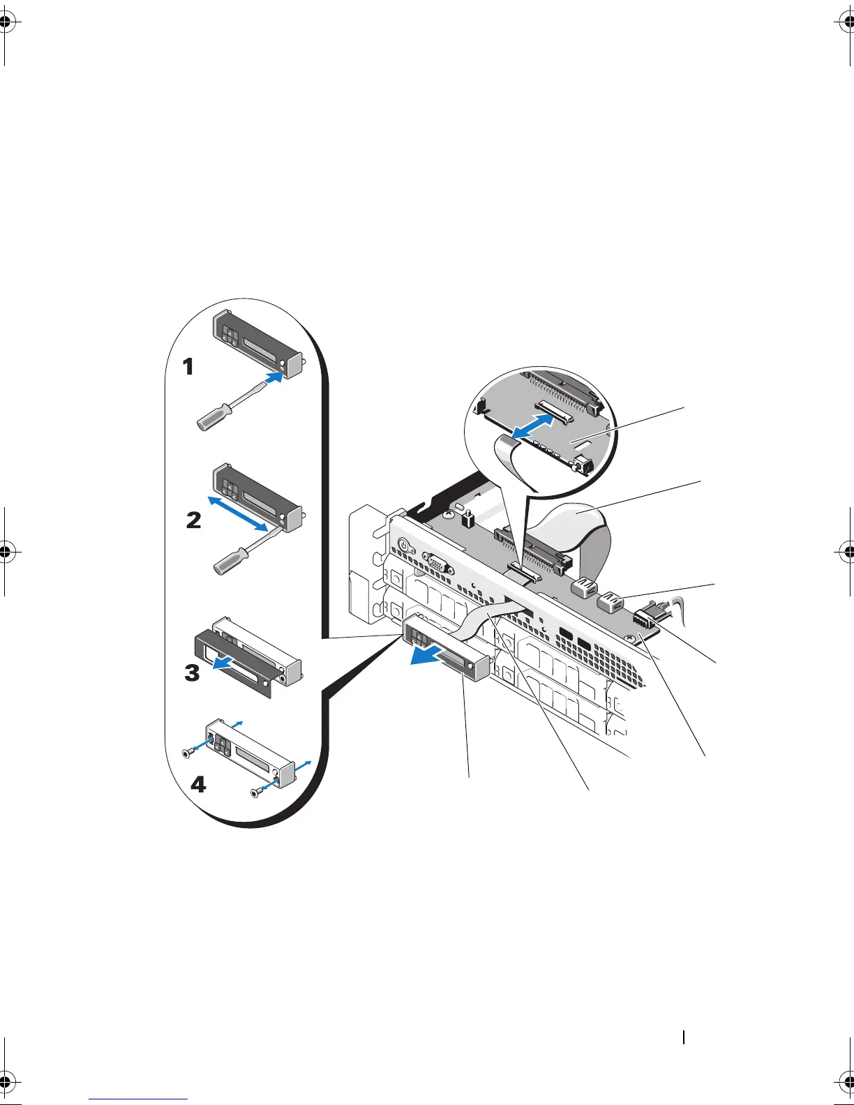
Disconnect the display module cable from the control panel board. See
Figure 3-32.
7
Remove the two Phillips screws that secure the control panel board to the
system chassis and remove the board.
Figure 3-32. Removing and Installing the Control Panel—LCD
1 slot 2 control panel cable
3 USB memory key connector 4 power cable
5 control panel board 6 display module cable
7 LCD display module
book.book Page 153 Friday, November 20, 2009 2:56 PM

 Loading...