64 Installing System Components
5
Open the processor cover by sliding the release lever from under the release lever latch on the socket.
Then, pull the lever back to release the processor. See Figure 3-16.
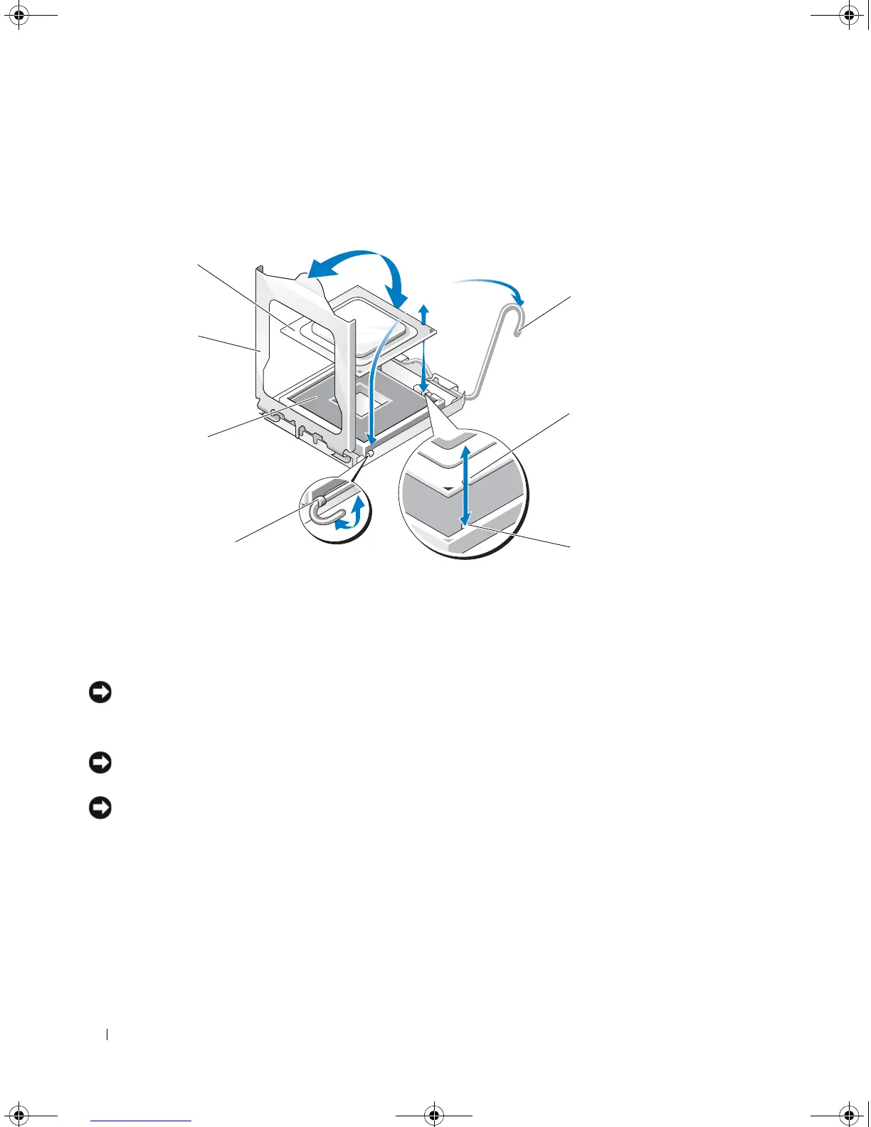
Figure 3-16. Installing and Removing a Processor
NOTICE: The retention latch is pressure-loaded. Ensure that the latch does not quickly open and strike the
processor or system board.
6
Carefully pivot the retention latch away from the processor.
NOTICE: Do not pry the processor from the socket by a single edge. This could result in damage to the processor’s
delicate connections.
NOTICE: Be careful not to touch or drop any foreign materials on the socket connector pads.
7
Lift the processor straight up and out of the socket.
Leave the release lever and retention latch in the release position so that the socket is ready for the new
processor.
1 processor 2 retention latch 3 socket
4 release lever latch 5 tab 6 notched processor edge
7 release lever
book.book Page 64 Tuesday, August 25, 2009 1:14 PM