Hardware and Initial Configuration 7
FILE LOCATION: C:\Users\gina\Desktop\Checkout_new\Maintenance Projects\Dell
Plasma\GSG\Plasma_UGHW&InitialConfiguration.fm
DELL CONFIDENTIAL – PRELIMINARY 3/6/13 - FOR PROOF ONLY
• Single Internal Out-of-Band port
The switch supports an Out-of-Band (OOB) port that is connected to the
management network of the chassis.
Port Naming Convention
There are 5 groups of ports, numbered 0-4. Group 0 represents the external
ports and groups 1-4 represents the internal ports that are connected to blade
servers 1-4.
External/Internal Ports
The following naming convention is used for internal and external ports:
gigabitethernet group/port_number or gi group/port_number
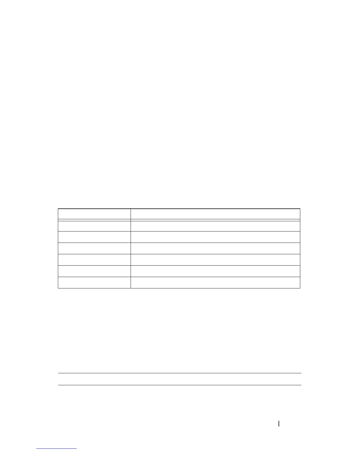
The following table maps the hardware network port numbers to the software
interface port numbers and describe how they are referred to in the CLI/GUI:
Front Panel LEDs
The front panel contains LEDs and ports, as follows:
•
2 System LEDs
— Status and Power.
These are described in Table 1-2.
•
8 ports
— Each having two associated LEDs.
These are described in
Ta ble 1 -3 .
Table 1-1. Port Mapping Table
Port Type and Number Software Port Naming Convention in CLI/WEB
External ports 1-8 gi0/1.... gi0/8
Internal ports 1-4 gi1/1.... gi1/4
Internal ports 5-8 gi2/1.... gi2/4
Internal ports 9-12 gi3/1.... gi3/4
Internal ports 13-16 gi4/1.... gi4/4
Out-of-Band port oob
Table 1-2. System LED’s
State of Switch Status LED Power LED (Green) Description
Off Off Off Switch is powered-
off.
 Loading...