Do you have a question about the Dell S2721H and is the answer not in the manual?
Open the carton and remove all accessories and packaging materials.
Remove screws and carefully pry open the rear cover using hand pressure.
Remove tapes, disconnect speaker cables, and unscrew speakers from the middle bezel.
Remove aluminum foil and detach the two speakers from the bezel.
Remove foils to unfix LVDS and disconnect function key/panel lamp cables.
Unscrew brackets attached to the middle and panel modules.
Remove thirteen screws to detach the middle bezel from the assembled unit.
Remove tape and lift the panel module from the bracket chassis.
Disconnect the LVDS cable from the panel module connector by releasing locks.
Remove the bracket chassis module and place it on a protective surface.
Detach the Mylar material from the hooks of the bracket chassis.
Unscrew six screws to release the circuit board and detach cables.
Carefully remove interface and power boards and disconnect all cables.
Detailed steps for removing electrolyte capacitors from circuit boards, including cutting glue and lifting.
Information on substances and components requiring separate disposal or recovery under WEEE directive.
List of tools typically needed for selective component and material removal during disassembly.
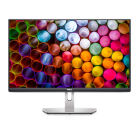
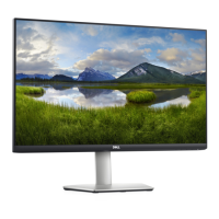
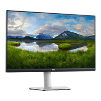
The DELL S2721H is a monitor designed for ease of use, maintenance, and responsible disposal. Its packaging and assembly are structured to facilitate straightforward setup and, when necessary, efficient disassembly for repair or recycling.
The DELL S2721H functions as a visual display unit, connecting to various devices to present digital content. It is designed to provide a clear and stable image for a range of applications, from everyday computing to more demanding visual tasks. The monitor is supported by a stand system that includes a base and a riser, allowing for stable placement on a desk or other flat surface. It integrates essential connectivity options, including an HDMI port, to ensure compatibility with common input sources. The monitor's internal components are carefully arranged to optimize performance and thermal management, with circuit boards and display modules working in concert to deliver the visual output.
The user experience begins with the packaging, which is designed for convenient access. The monitor comes in a "Pizza carton" that can be opened with a standard tool, revealing the contents in an organized manner. All necessary accessories for immediate use are included: a Quick Start Guide (QSG), an HDMI cable, a power cable, a CD with drivers or documentation, a user's manual, the stand base, the stand riser, and an EEI label. This comprehensive set ensures that users have everything they need to set up the monitor right out of the box.
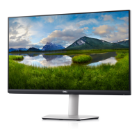
The monitor itself is protected during transit by molded pulp inserts for the base, riser, and cover, and is further enclosed in an EPE bag. Upon removal from the packaging, it is recommended to place the monitor on a protective cushion to prevent damage during setup. The stand system is designed for easy assembly, allowing users to quickly attach the base and riser to the monitor for stable positioning.
Once set up, the monitor is ready to connect to a power source and an input device via the HDMI cable. The intuitive design aims to minimize the complexity of initial setup, allowing users to quickly integrate the monitor into their workspace. The overall user experience emphasizes simplicity and readiness for immediate operation.
The DELL S2721H is engineered with an emphasis on modularity and accessibility, which significantly aids in maintenance, repair, and end-of-life recycling. The disassembly process is clearly outlined, indicating a design philosophy that supports responsible product lifecycle management.
The initial steps of maintenance or repair involve accessing the internal components. The rear cover of the monitor is designed to be removed by wedging fingers between it and the middle bezel at the top corners. This action releases the cover, which can then be carefully pulled up, following a specific sequence indicated by arrows to unlock its mechanisms. This method avoids the need for specialized tools for the initial opening, making it more accessible.
Further disassembly requires standard tools, primarily a Philips-head screwdriver. Multiple sets of screws are used throughout the monitor's construction, each with specified sizes and torque values, which are crucial for proper reassembly and maintaining structural integrity. For instance, removing the rear cover involves six screws of specific dimensions and torque.
Internal components are also designed for easy access and removal. Speakers are secured with screws and connected via cables, which can be disconnected after tearing off acetate tapes. The middle bezel, which frames the display, is secured by 13 screws, allowing it to be separated from the assembled unit. The function key board, an essential interface component, is also secured with screws and tapes, which can be released to access or replace the key cables.
The panel module, the core display component, is designed to be lifted from the bracket chassis after releasing the front bezel. This separation is facilitated by tearing off a specific tape. Connectivity within the monitor is also designed for maintainability. The LVDS cable, which transmits video signals, can be unplugged from the panel module by pushing its earing-locks. Similarly, other cables, such as the function key cable and the panel lamp cable, are connected via connectors and secured with acetate tape, making them straightforward to disconnect.
The bracket chassis module, which houses the circuit boards, can be removed and placed on a protective cushion for further work. The Mylar, a protective film, can be removed from the hooks of the bracket chassis module. The circuit boards themselves, including the interface board and power board, are secured by screws and can be carefully removed after releasing all cables from their hooks. This modular approach ensures that specific components can be isolated and serviced without extensive dismantling of the entire unit.
For component-level maintenance, such as replacing electrolyte capacitors on printed circuit boards, the design provides clear instructions. The glue securing bulk capacitors to the PCB can be cut with a knife, ensuring that the cutting path remains within the glue to avoid damaging the capacitor or the board. The process involves cutting into the bottom of the bulk cap and carefully pulling it up. Subsequently, the bulk cap's pin solder can be removed using a soldering iron and an absorber, allowing the capacitor to be lifted away from the PCB.
The product material information also highlights components that require selective treatment for disposal, such as printed circuit boards, LCD displays, external electric cables, and electrolyte capacitors. This information is crucial for compliance with environmental directives and promotes responsible recycling practices. The tools required for disassembly are common, including Philips-head screwdrivers of different sizes, a penknife, and a soldering iron with an absorber, making the maintenance process accessible to technicians.
| Pixel pitch | 0.3114 x 0.3114 mm |
|---|---|
| Screen shape | Flat |
| Pixel density | 81.59 ppi |
| Response time | 8 ms |
| Backlight type | LED |
| Display diagonal | 27 \ |
| Display technology | LCD |
| Native aspect ratio | 16:9 |
| Vertical scan range | 48 - 75 Hz |
| Maximum refresh rate | 60 Hz |
| Response time (fast) | 5 ms |
| Horizontal scan range | 30 - 83 kHz |
| Supported video modes | 480i, 480p, 576i, 576p, 720p, 1080i, 1080p |
| NTSC coverage (typical) | 72 % |
| Viewable size, vertical | 336.31 mm |
| Contrast ratio (typical) | 1000:1 |
| Display number of colors | 16.78 million colors |
| Viewable size, horizontal | 597.89 mm |
| Display brightness (typical) | 300 cd/m² |
| Supported graphics resolutions | 640 x 480 (VGA), 720 x 400, 800 x 600 (SVGA), 1024 x 768 (XGA), 1152 x 864 (XGA+), 1280 x 1024 (SXGA), 1600 x 900, 1920 x 1080 (HD 1080) |
| AMD FreeSync | Yes |
| RMS rated power | 6 W |
| Number of speakers | 2 |
| Product color | Gray |
| Front bezel color | Black |
| Heavy metals free | Pb (lead) |
| Market positioning | Business |
| Sustainability certificates | RoHS, ENERGY STAR |
| HDMI version | 1.4 |
| Headphone outputs | 1 |
| DisplayPorts quantity | 0 |
| Headphone connectivity | 3.5 mm |
| LED indicators | Power |
| Tilt angle range | -5 - 21 ° |
| Panel mounting interface | 100 x 100 mm |
| Input current | 1.5 A |
| AC input voltage | 100 - 240 V |
| Power supply type | Internal |
| AC input frequency | 50 - 60 Hz |
| Power consumption (max) | 41 W |
| Annual energy consumption | 27 kWh |
| Power consumption (standby) | 0.2 W |
| Power consumption (typical) | 16.8 W |
| Operating altitude | 0 - 5000 m |
| Non-operating altitude | 0 - 12192 m |
| Storage temperature (T-T) | -20 - 60 °C |
| Operating temperature (T-T) | 0 - 40 °C |
| Storage relative humidity (H-H) | 5 - 90 % |
| Operating relative humidity (H-H) | 10 - 80 % |
| Package depth | 720.09 mm |
| Package width | 135.89 mm |
| Package height | 447.04 mm |
| Package weight | 7700 g |
| Cables included | AC, HDMI |
| Harmonized System (HS) code | 85285210 |
| Bezel width (side) | 6 mm |
|---|---|
| Depth (with stand) | 186.8 mm |
| Height (with stand) | 453.3 mm |
| Weight (with stand) | 5400 g |
| Bezel width (bottom) | 21.3 mm |
| Depth (without stand) | 54 mm |
| Width (without stand) | 609.9 mm |
| Height (without stand) | 363.6 mm |
| Weight (without stand) | 4400 g |