Do you have a question about the Dell S2721HN and is the answer not in the manual?
Open the carton and remove accessories like QSG, cables, and stand.
Remove molded pulp, base, riser, cover, and the monitor.
Remove 6 screws for unlocking mechanisms using a Philips-head screwdriver.
Release the rear cover by wedging fingers and carefully pulling it upwards.
Disconnect panel lamp and function key cables from their connectors.
Remove 18 screws to unlock the middle bezel using a Philips-head screwdriver.
Remove screws securing the bracket with middle bezel and panel module.
Remove the middle bezel and screws for the function key board.
Lift the panel module with bracket chassis and release the front bezel.
Unplug the LVDS cable from the panel module connector by pushing ear-locks.
Move the bracket chassis module onto a protective cushion.
Remove the Mylar sheet from the hooks of the bracket chassis module.
Remove 5 screws to unlock the circuit board and release cables.
Carefully remove interface and power boards, disconnecting all cables.
Remove electrolyte capacitors from printed circuit boards using cutting and desoldering.
Details substances and components requiring separate disposal or recovery under EU directives.
Lists tools needed for disassembly, including screwdrivers, penknife, and soldering equipment.
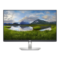
This document outlines the disassembly procedures and material information for the S2721HN/NX device, providing a comprehensive guide for technicians and users interested in its internal components and maintenance. The device appears to be a monitor, given the references to a "panel module," "rear cover," "middle bezel," and "function key board."
The S2721HN/NX is a display device, likely a computer monitor, designed for visual output. Its core function involves presenting visual information to the user, supported by an LCD display. The internal architecture includes an interface board and a power board, which are crucial for processing video signals and supplying necessary power to the various components. The presence of a "panel module" and "function key board" indicates that the device is capable of displaying images and allowing user interaction for settings adjustments. The mention of an HDMI cable as an accessory suggests its primary input for video signals, making it compatible with a wide range of modern computing devices.
The device is packaged in a "Pizza carton," implying a user-friendly unboxing experience. The initial steps involve carefully opening the carton and removing accessories such as a Quick Start Guide (QSG), HDMI cable, power cable, CD & user's manual, stand base, stand riser, and an EEI label. The inclusion of a stand base and riser indicates that the monitor is designed to be placed on a desk or flat surface, with adjustable height or tilt options for ergonomic viewing. The "function key board" allows users to navigate menus and adjust settings, providing control over display parameters like brightness, contrast, and input source. The device's design, with a "rear cover" and "middle bezel," suggests a sleek and integrated appearance when fully assembled. The instructions for releasing the rear cover and accessing internal components highlight a design that, while requiring tools for full disassembly, is structured for potential servicing or repair.
The manual provides detailed instructions for disassembling the S2721HN/NX, which is essential for maintenance, repair, or recycling purposes. The process begins with removing the rear cover, which is secured by six Philips-head screws. This initial step grants access to the internal components. Further disassembly involves removing the middle bezel, secured by eighteen screws, and then detaching the bracket with the middle bezel and the panel module, each secured by additional screws. The instructions also detail how to unplug various cables, such as the panel lamp cable, function key cable, and LVDS cable, which are critical for isolating and replacing specific components.
A significant aspect of the maintenance instructions focuses on the removal of electrolyte capacitors from the printed circuit boards. This process is detailed with specific steps:
These detailed steps for capacitor removal are crucial for component replacement, especially in cases of power supply issues, which are often linked to faulty capacitors. The document also lists specific tools required for disassembly, including Philips-head screwdrivers (#1 and #2), a penknife, and a soldering iron with an absorber. This comprehensive list ensures that technicians have the necessary equipment to perform maintenance tasks effectively. The information on product material, including the presence of an LCD display greater than 100 cm² and external cables, is vital for proper recycling and disposal in accordance with environmental regulations, particularly EU Council Directive 75/442/EEC. The explicit mention of "no used" for various hazardous substances like mercury, asbestos, and CFCs indicates a design conscious of environmental impact, simplifying disposal procedures for these materials. The presence of electrolyte capacitors (height > 25mm, diameter > 25mm) is also noted, highlighting a specific component that requires selective treatment during recycling.
| Color gamut | 72 % |
|---|---|
| Pixel pitch | 0.3114 x 0.3114 mm |
| Screen shape | Flat |
| Pixel density | 81.59 ppi |
| Response time | 8 ms |
| Backlight type | LED |
| Display diagonal | 27 \ |
| Display technology | LCD |
| Native aspect ratio | 16:9 |
| Vertical scan range | 48 - 75 Hz |
| Maximum refresh rate | 60 Hz |
| Response time (fast) | 5 ms |
| Horizontal scan range | 30 - 83 kHz |
| Supported video modes | 480i, 480p, 576i, 576p, 720p, 1080i, 1080p |
| Viewable size, vertical | 336.31 mm |
| Contrast ratio (typical) | 1000:1 |
| Display number of colors | 16.78 million colors |
| Display brightness (typical) | 300 cd/m² |
| Supported graphics resolutions | 640 x 480 (VGA), 720 x 400, 800 x 600 (SVGA), 1024 x 768 (XGA), 1152 x 864 (XGA+), 1280 x 1024 (SXGA), 1600 x 900, 1920 x 1080 (HD 1080) |
| AMD FreeSync | Yes |
| Product color | Black |
| Heavy metals free | Pb (lead) |
| Market positioning | Business |
| Sustainability certificates | RoHS, ENERGY STAR |
| HDMI version | 1.4 |
| Headphone outputs | 1 |
| DisplayPorts quantity | 0 |
| Headphone connectivity | 3.5 mm |
| LED indicators | Power |
| Tilt angle range | -5 - 21 ° |
| Panel mounting interface | 100 x 100 mm |
| Input current | 1.5 A |
| AC input voltage | 100 - 240 V |
| Power supply type | Internal |
| AC input frequency | 50 - 60 Hz |
| Energy efficiency scale | A to G |
| Power consumption (max) | 29 W |
| Annual energy consumption | 23 kWh |
| Power consumption (standby) | 0.2 W |
| Power consumption (typical) | 15.5 W |
| Operating altitude | 0 - 5000 m |
| Non-operating altitude | 0 - 12192 m |
| Storage temperature (T-T) | -20 - 60 °C |
| Operating temperature (T-T) | 0 - 40 °C |
| Storage relative humidity (H-H) | 5 - 90 % |
| Operating relative humidity (H-H) | 10 - 80 % |
| Package depth | 720.09 mm |
| Package width | 135.89 mm |
| Package height | 447.04 mm |
| Package weight | 7600 g |
| Cables included | AC, HDMI |
| Harmonized System (HS) code | 85285210 |
| Bezel width (side) | 6 mm |
|---|---|
| Depth (with stand) | 186.8 mm |
| Height (with stand) | 453.3 mm |
| Weight (with stand) | 5200 g |
| Bezel width (bottom) | 21.3 mm |
| Depth (without stand) | 54 mm |
| Width (without stand) | 609.9 mm |
| Height (without stand) | 363.6 mm |
| Weight (without stand) | 4300 g |