4. Disassembly and Assembly Procedures
S9
S8
S10
S11
S7
U
U
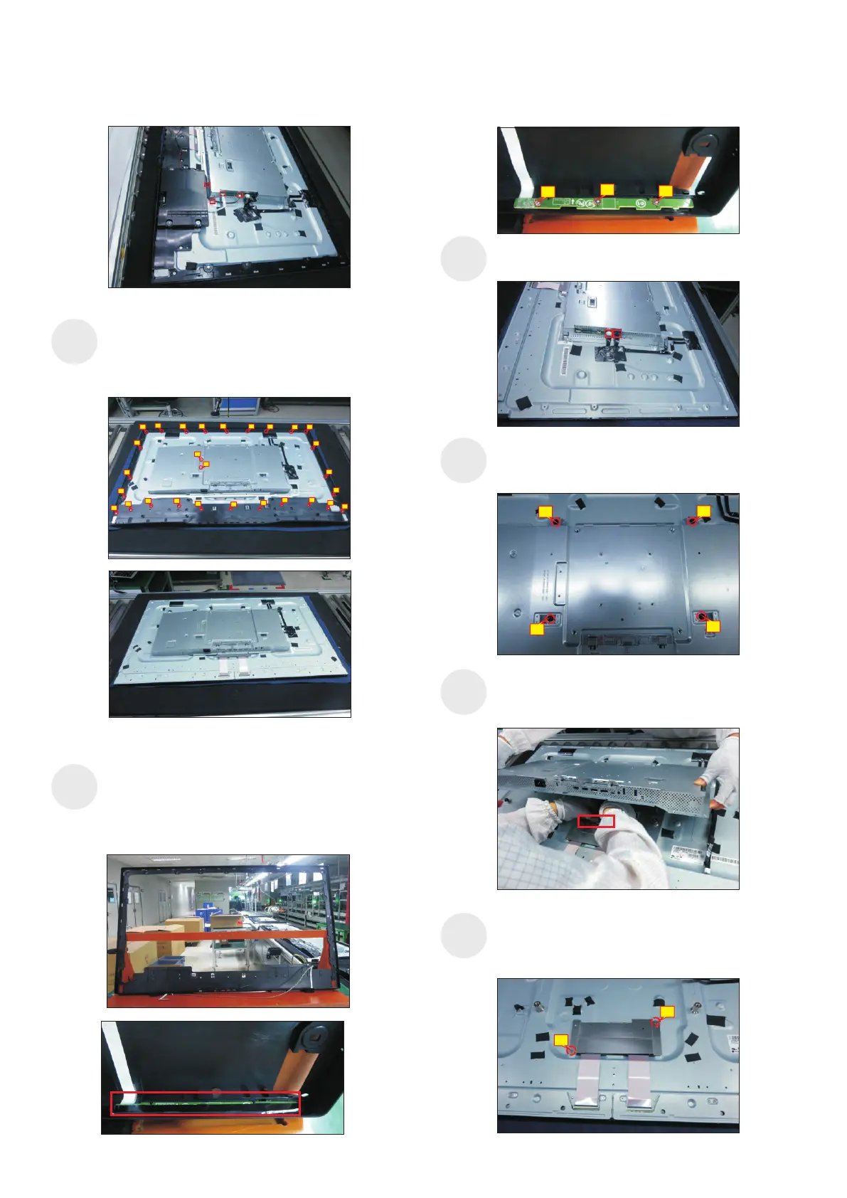
se a Philips-head screwdriver to remove 2pcs
screws for unlocking the heat-sink. se a Philips-
head screwdriver to remove 26pcs screws for
unlocking the middle bezel, then remove the bezel.
(No.1~28 Screw size= M3x0.5x4, Torque=5±0.5kgfxcm)
1
2
78
9
13
14
15
3
4 5
6
10
11
12
21
20
19
18
17
16
22
23
24
25
26
28
27
Put the rear cover with function key board into a Jip.
Tear off the mylar tape on the function key board,
then use a Philips-head screwdriver to tighten 3pcs
screws for locking the function key board with the
front bezel.
(No.1~3 Screw size= M2x2.4, Torque=0.8±0.2kgfxcm)
Tear off acetate tape, then disconnect the panel lamp
cables from the connectors of the circuit board.
U
.
se a Philips-head screwdriver to remove 4pcs screws
for locking the bracket chassis module with the panel
(No.1~4 Screw size= M6x12, Torque=9±0.5kgfxcm)
Lift up the bracket chassis, and disconnect the LVDS
cable from the connector of the T-CON board, then
put the bracket chassis on a protective cushion.
2
3
4
1
Use a Philips-head screwdriver to remove 2pcs
screws for unlocking the small bracket with T-Con
board, then remove the small bracket.
(No.1~2 Screw size= M3x0.5x4, Torque=3~5kgfxcm)
2
1
S12
1
2
3