4. Disassembly and Assembly Procedures
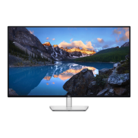
S15
Take a pair of speakers to locate the probers of the
middle bezel, then locate the speakers’ cable to the
hooks of the middle bezel, and then connect the
speaker cable to the connector of the circuit board.
Use a Philips-head screwdriver to tighten 8pcs
screws for locking the speakers with middle bezel.
(No.1~8 screw size=M3x8, Torque=5±0.5kgfxcm)
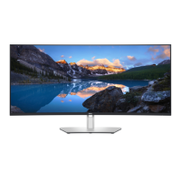
S14
Move the assembled rear cover close to the
panel unit, then connect the USB LVDS cable and
function key cable to the connectors of interface
board. Put down the rear cover and push the rear
cover on the positions marked as the picture
below shown for mechanisms engagement.
1
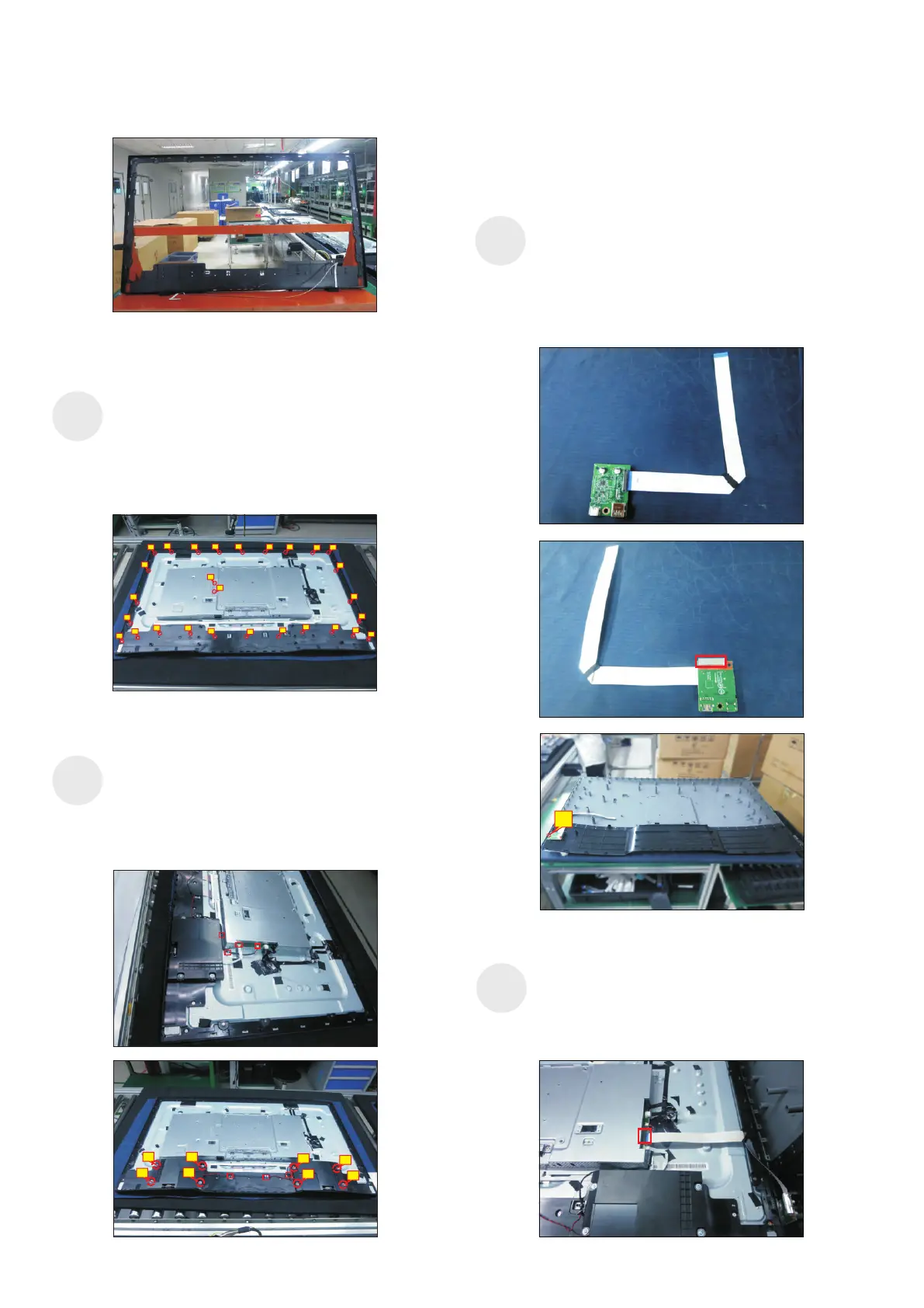
S16
2
6
7
8
5
3
4
1
Take 1pcs USB board, 1pcs conductive foam, 1pcs
LVDS cable and 1pcs rear cover. Connect the LVDS
cable to the connector of the USB board, then paste
1pcs conductive foam on the back of the USB board,
and then locate the USB board into the correct
position of the rear cover. Use a Philips-head
screwdriver to tighten 1pcs screw for locking the
USB unit with the rear cover.
(No.1 screw size=M3x6, Torque=4±0.5kgfxcm)
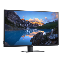
Assemble the middle
the unit, then settle and paste the function key cable
with tapes as the picture below shown. U
U
bezel with function key board to
se a Philips-
head screwdriver to tighten 26pcs screws for locking
the middle bezel with the panel module. se a
Philips-head screwdriver to lock 2pcs screws for
locking the heat-sink.
(No.1~28 Screw size= M3x0.5x4, Torque=5±0.5kgfxcm)
S13
1
2
78
9
13
14
15
3
4 5
6
10
11
12
21
20
19
18
17
16
22
23
24
25
26
28
27