Steps
1. Remove the two (M2.5x5) screws from the right hinge.
2. Pry open the right-display hinge at an angle of 90 degrees.
3. Disconnect the following cables from the system board:
a. I/O board Flexible Flat cable
b. Speaker cable
c. Touchpad Flexible Flat cable
d. Keyboard backlight Flexible Printed cable (for systems with backlit keyboard)
e. Keyboard Flexible Printed cable
f. Power adapter port cable
g. eDP cable
4. Remove the four (M2x3.5) screws that secure the system board to the palm-rest assembly.
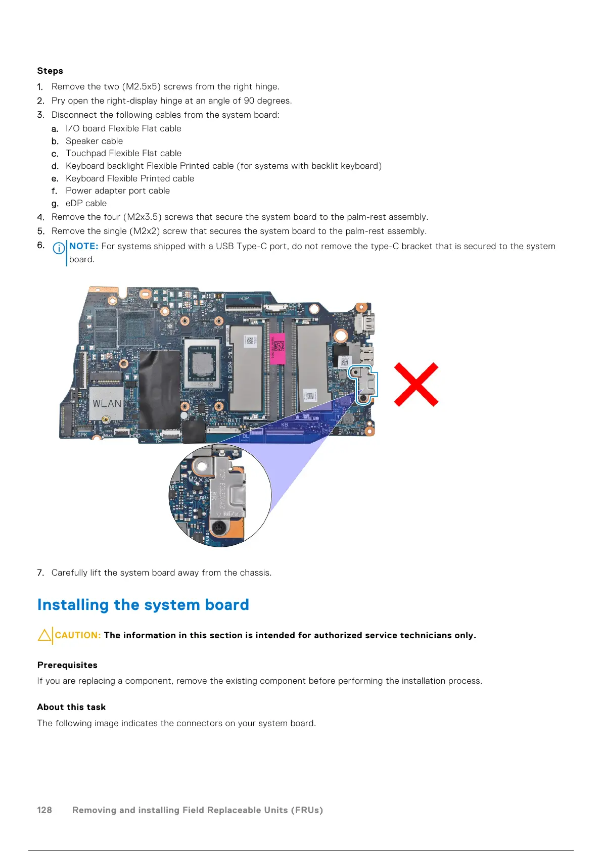
5. Remove the single (M2x2) screw that secures the system board to the palm-rest assembly.
6.
NOTE: For systems shipped with a USB Type-C port, do not remove the type-C bracket that is secured to the system
board.
7. Carefully lift the system board away from the chassis.
Installing the system board
CAUTION: The information in this section is intended for authorized service technicians only.
Prerequisites
If you are replacing a component, remove the existing component before performing the installation process.
About this task
The following image indicates the connectors on your system board.
128
Removing and installing Field Replaceable Units (FRUs)
129 / 156 128 / 154 129 / 156
 Loading...