5
For both backplane and LAN networks on the cluster, the interfaces are in an Active /Passive bond, and
not in a team or Active/ Active bond.
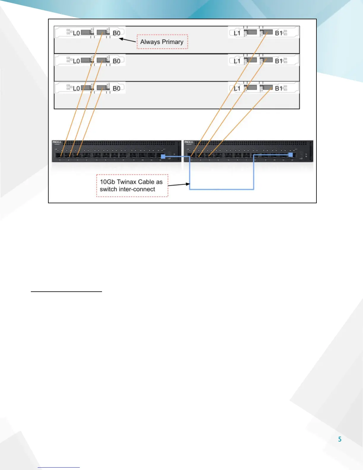
Looking at the back of the node, the interfaces labeled “L0” and “B0” are the primary LAN and
Backplane interfaces respectively (L0 is the primary LAN and B0 is the primary backplane interface).
These interfaces will always be primary. The secondary interfaces are “L1” and “B1.” It is vital to ensure
that all primary interfaces and secondary interfaces are connected to separate switches to avoid loops
or additional network hops for backplane trafc.
Cable the Nodes
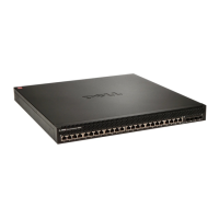
Using 10 GbE SFP+ Twinax cabling, connect the backplane interfaces “B0” on each node to ports 1, 2, and
3 on the X4012 switch.
Then, connect the second “B1” interfaces to ports 1 , 2, and 3 on the second X4012 switch. An example
is shown in the image on the next page.