DELTA ELEKTRONIKA BV ES150
Page 5 - 1 OPERATING MAINTENANCE TROUBLE SHOOTING rev. March 2017
DESCRIPTIONS
1) RE MOTE SENSING
The volt age at the load can be kept con stant by re mote sens -
ing. This fea ture is not rec om mended for nor mal use but only
when the load volt age is not al lowed to vary more than a few
mil li volts. Al ways use a shielded ca ble for sens ing.
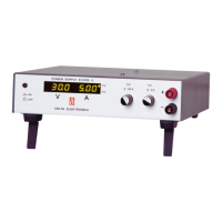
In or der to com pen sate for the volt age drop across the load
leads, the unit will have to sup ply a higher volt age: Uout =
(volt age drop across each lead) + (volt age across the load)
(see fig. 5 - 1).
The volt age dis play is con nected to the sense leads and
there fore reads the volt age across the load and not the volt -
age on the out put ter mi nals.
The sense leads are pro tected for ac ci den tal in ter rup tion, in
which case the out put volt age will go to a max. of 115% of the
set value.
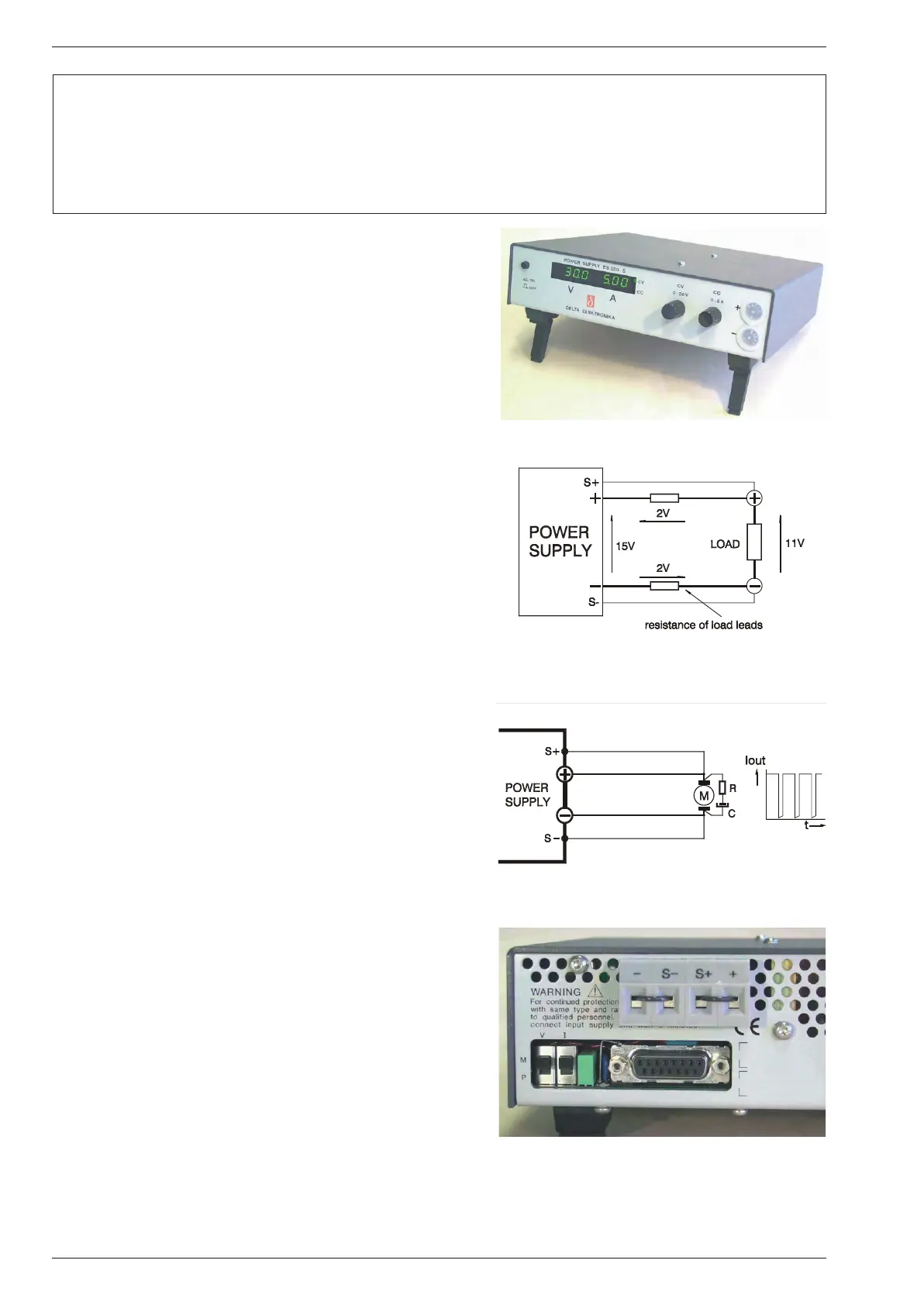
2) PUL SATING LOAD
When us ing re mote sens ing on a pul sat ing load (for in stance
a DC-mo tor), use a ca pac i tor be tween S+ and + and be tween
S– and – and a se ries re sis tor in the sense leads (see fig. 5 -
2). Like this the AC-com po nent caused by the volt age drop
across the load leads, is fil tered.
OPERATING
1) RE MOTE SENSING
Re move the links on the TER MI NAL BLOCK (on rear panel)
and con nect sense leads (thin shielded mea sur ing wires) to
S+ and S– (see fig. 5 - 4).
With re mote sens ing the volt age on the load can be kept con -
stant. The volt age drop across the load leads will be com pen -
sated. This fea ture is not rec om mended for nor mal use,
be cause it can eas ily give prob lems.
Max. 2 V per load lead can be com pen sated. Note that the
volt age drop in the leads de creases the max. out put volt age
rat ing. In fig. 5 - 1 it can be seen that on a 15 V power sup ply
only 11 V will be avail able on the load when 2x 2 V com pen sa -
tion is used.
In or der to pre vent in ter fer ence it is ad vis able to use shielded
ca ble for the sense leads. The in duc tance of the loads leads
could give a prob lem with pul sat ing loads. In this case a large
elec tro lytic ca pac i tor in par al lel with the load will help. Check
that the ca pac i tor in com bi na tion with the load leads does not
form a res o nant cir cuit re sult ing in a large AC cur rent flow ing
in the leads.
Since the volt age dis play is in ter nally con nected to the sens -
ing ter mi nals, it will au to mat i cally in di cate the volt age on the
load. Note that the volt age mea sured on the load will be lower
than on the out put ter mi nals.
2) MASTER / SLAVE PAR AL LEL OP ER A TION
WITH SENSE OPTIONS
Dis con nect the links be tween the S– and – of the slaves only.
If not re moved the cur rent sharing will not be pro por tional.
The S– and S+ could be con nected to the load if de sired, but
this is not rec om mended be cause of the com plex ity.
REMOTE SENSING for the ES 150 - series
ES 015-10 OP TION P119
ES 030-5 OP TION P120
ES 075-2 OP TION P121
ES 0300-0.45 OP TION P122
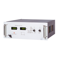
With the RE MOTE SENSING op tions, the power
con nec tors are moved to the rear panel
fig. 5 - 1
With re mote sens ing the volt age drop in the
load subtracts from the max i mum out put
fig. 5 - 2
Re mote sens ing on a pul sat ing load
fig. 5 - 3
On the ter mi nal block, the +, S+, – and S– wires
must be con nected. When us ing the power sup ply
with out sens ing, the links be tween + and S+ and –
and S– must be in serted.
 Loading...