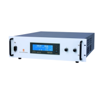
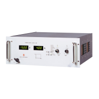
Do you have a question about the Delta Elektronika SM1500 Series and is the answer not in the manual?
| Brand | Delta Elektronika |
|---|---|
| Model | SM1500 Series |
| Category | Power Supply |
| Language | English |
Essential safety precautions for operation, service, and repair of the equipment.
Specifies the installation category II for overvoltage protection.
Requirements for connecting AC power terminals to an electrical ground for safety.
Safety guidelines for grounding DC power terminals and associated connections.
Warning about potential electrical shock from charged capacitors or residual voltage.
Instructions for connecting the unit to the mains supply.
Specifies that fuses should only be replaced by authorized service personnel.
Warning against using AC supply exceeding the unit's voltage and frequency ratings.
Prohibits unauthorized personnel from removing covers or making internal adjustments.
Parts substitutions and modifications are restricted to authorized personnel.
Procedures for safely removing safety covers, including power disconnection.
Safety guidelines for handling the unit's weight and sharp edges.
Warnings about hot fan exhausts and obstructing fan openings.
Warning about strong magnetic fields affecting medical devices.
Defines acceptable operating conditions, including temperature and humidity.
Explains important safety symbols and markings used on the instrument.
Statement of compliance with Canadian safety standards.
Indicates product certification by TÜV Rheinland.
Guidance on responsible disposal and recycling of the product.
Details DC output modes, autoranging facility, and output ranges.
Information on the wide AC input voltage range and power derating.
Details active power factor correction and electronically limited inrush current.
Notes the unit's low power consumption when in standby mode.
Emphasizes high efficiency, leading to low power loss and heat generation.
Specifies CV load regulation is measured directly on DC power terminals.
Recommendations for accurate CC load regulation, avoiding external voltage sensing.
Details the low DC output ripple and noise, and measurement methods.
Describes programming DC output voltage and current via external analog voltage.
Methods to prevent earth loops for programming using isolated sources.
Availability of optional controllers for programming via digital interfaces.
Explains monitor outputs providing voltage proportional to output current or voltage.
Information on the +12V output available on the programming connector.
Details logic outputs that indicate various status conditions of the unit.
Describes the two status relay outputs with change-over contacts.
Explains the functions of the DIP switches located on the rear panel.
Describes how to shut down the unit's output remotely.
Details the interlock connector function for safety and emergency stop.
Information on programming speed, rise/fall times, and options.
Recommendations for managing pulsating loads to prevent overheating.
Information on insulation test voltages applied to separating components.
Details RFI filters on input and output for reduced conducted RFI.
Specifies the operating temperature range and derating at higher temperatures.
Describes the thermal protection feature that shuts down the output on overheating.
Explains how load and output voltage affect the unit's hold-up time.
States the approximate turn-on delay for the DC output voltage.
Explains that AC inrush current is electronically limited.
Detailed instructions for connecting and using DC load sensing.
Instructions for connecting power supplies in series for higher voltage output.
Guidelines for connecting power supplies in parallel for higher current output.
Describes how to use multiple units as building blocks in master/slave configurations.
Explains setting and using voltage and current limits for circuit protection.
Details front panel controls, including potentiometers and optional encoders.
Describes the cooling fan system, airflow tunnel, and stacking capabilities.
Presents the physical dimensions of the power supply unit.
Precautions regarding humidity and preventing condensation inside the unit.
Specifies storage and operating temperature ranges and cooling requirements.
Guidelines for mounting the unit in a standard 19-inch rack.
Step-by-step guide for first-time operation of the power supply unit.
Instructions for activating and deactivating the front panel keylock function.
How to select the unit's start-up mode using DIP switch SW1-5.
Steps for setting up and using analog programming via the rear panel connector.
Instructions for programming using the optional ISO AMP CARD.
Configuration for programming via IEEE488 or RS232 interfaces.
Information on using the monitoring outputs with other interfaces.
Specifics about the status outputs and their connections.
Detailed instructions for connecting and using DC load sensing.
Explains how the power supplies can be used as ideal battery chargers.
Methods for implementing remote shutdown using voltage or relay contacts.
How to connect units in series for master/slave operation.
How to connect units in parallel for master/slave operation.
Notes on parallel operation for high-speed programming versions.
Guidance for complex mixed series-parallel master/slave configurations.
General guidance for contacting support and preparing for unit repair.
Steps to troubleshoot the absence of DC output when operating in manual control.
Diagnosing and resolving issues when programming does not function correctly.
Identifies causes of unwanted programming offsets, like earth loops.
Steps to troubleshoot failures related to status outputs.
Addresses potential problems in master/slave parallel configurations.
Steps to troubleshoot when the DC output voltage exceeds the set value.
Explains the cause of the OT LED being on, related to overheating.
Explains the cause of the OT LED blinking, indicating rising temperature.
Addresses issues when the ACF LED is on, related to input voltage.
Explains reasons for the DCF LED being on, related to output voltage or interlock.
Addresses issues when the PSOL LED is on, related to Power Sink overload.
Identifies blinking control LEDs as an indication of Keylock activation.
Guidance for troubleshooting when no LEDs are illuminated on the unit.
General advice for persisting problems, directing to the RMA form.
General statement that power supplies require no specific maintenance or calibration.
Advice on inspecting and maintaining the cooling fan and heat sink.
Recommendations for using units in aggressive galvanic industry environments.
States units are factory calibrated and calibration is rarely needed.
How to calibrate the unit's digital meters using potentiometers.
Details special calibration procedures for specific components, requiring qualified personnel.


 Loading...