GENERAL SM1500
10 / 22 DELTA ELEKTRONIKA B.V. rev. Jan. 2021
Warning! The 3750 Vrms cannot be tested afterwards on the
assembled unit because the insulation between the
components on the AC side to the case (like the bridge
rectifier) is specified at 2500 Vrms. Since the insulation of DC
power terminals -> case is 600 VDC, the insulation of the
primary components to case will break down when 3750 Vrms
is applied between mains in and DC output (2500 Vrms + 600
VDC < 3750 Vrms) (see also fig. 3 - 15).
Note: when testing the insulation, take care to charge and
discharge the capacitors between mains in - case and DC
output - case slowly (e.g. in one second). This to prevent high
peak currents, which could destroy the power supply. Make
sure to discharge the capacitors completely before using it
again.
3.22
Both the mains input and DC output have RFI filters, resulting
in very low conducted RFI to the line and load. Due to the
output filter, the output voltage is very clean with almost no
spikes.
3.23
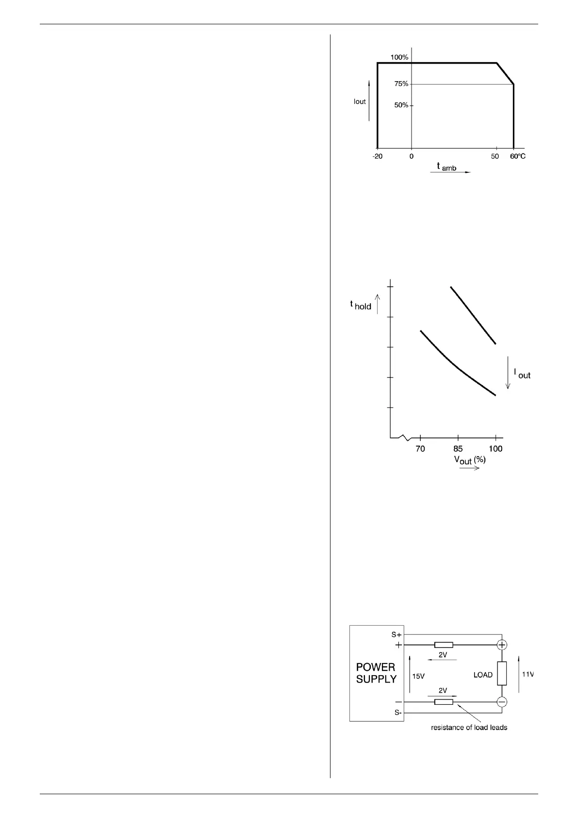
At full power the operating temperature range is –20 to
+50 °C. From 50 to 60 °C the DC output current has to be
derated linearly to 75 % at 60 °C (see fig. 3 - 16). These
temperatures hold for normal use, i.e. the ventilation openings
on the left and right side must be free.
3.24
A thermal switch shuts down the DC output in case of
insufficient cooling. The OT status will be high. After cooling
down the unit will start working again.
The OT-LED on the front panel will be on and the OT-status
signal will be "1" in case of a tripped thermal protection.
As a pre-warning the OT-LED blinks (status will still be low),
this will start before the power supply shuts down.
3.25
The hold - up time depends on the load and the DC output
voltage.
A lighter load or a lower DC output voltage results in a longer
hold - up time (see fig. 3 - 17).
3.26
The DC output voltage is available about 0.2 sec after mains
switch on.
3.27
The inrush current is electronically limited.
Repeatedly switching on and off does not change the
maximum peak current.
Switching on and off at a fast rate can overheat the inrush
current limiter. With the result that the unit does not start
anymore. After cooling down (mains switched off) it will be OK
again.
3.28
DC LOAD SENSING (REMOTE SENSING)
The DC voltage at the load can be kept constant by remote
sensing. This feature is not recommended for normal use but
only when the load voltage is not allowed to vary a few
millivolts. Always use a shielded cable for sensing.
In order to compensate for voltage drop across the load
leads, the unit will have to supply a higher voltage (fig. 3 - 18):
* Uout = (voltage drop across each lead) + (voltage across the load).
The voltage limit reads the voltage directly at the output
terminals. The setting for the limit must therefore be increased
by the total voltage drop across the load leads.
The voltage display on the front panel and the voltage monitor
output on CON E are connected to the sense leads and
therefore read the voltage across the load and not the voltage
on the DC output terminals.
fig 3 - 16
Operating temperature ranges.
fig 3 - 17
Hold-up time vs V
out
with I
out
as a parameter.
fig 3 - 18
Remote sensing, voltage drop in load leads subtracts
from maximum output.
 Loading...


