GENERAL SM1500
9 / 22 DELTA ELEKTRONIKA B.V. rev. Jan. 2021
The power supply has 2 status relay outputs, with each a
change-over contact. They are connected to connector CON
D. The pins 1,2,3 are connected to the DCF-relay and pins
4,5,6 to the ACF-relay (see fig. 3 - 8 and 3 - 10).
3.16
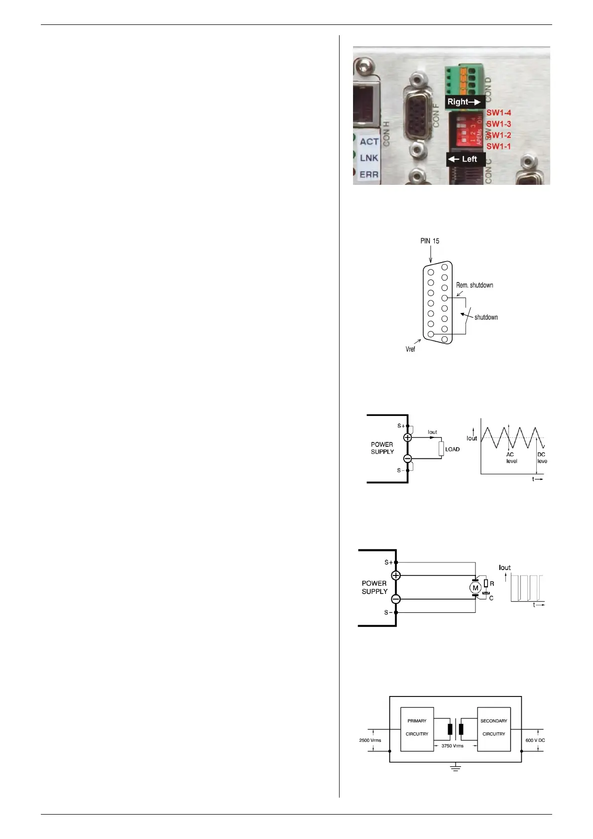
FUNCTION SWITCHES ON SW1
In the table on the previous page the functions of the DIP
switches 1-5 of switch SW1 at the rear side are explained.
3.17
A voltage of +4...+12 V on the RSD input on the programming
connector CON E will switch off the output of the unit.
It is also possible to use a relay contact or a switch to shut the
unit down (see fig. 3 - 11). In standby mode the power supply
consumes very little power.
3.18
The Interlock connector CON A has 2 pins which have to be
connected together to enable the unit.
As soon this connection is interrupted, the DC output of the
unit shuts down. It can be used in combination with door
contacts (safety precaution) or as an emergency stop.
In case the connection is interrupted the RSD LED will light.
In contrast with Remote ShutDown, also the DCF LED will be
on, DCF status will be high and the relay contact will change.
Once the inputs are reconnected, the DC output will be on
again.
The interlock circuit is at the same level as the analog ground,
the S- and the minus DC power terminal. The interlock circuit
needs voltage free contacts and can not be connected in
parallel or series with other interlocks .
3.19
The rise and fall time is measured with a step waveform at the
CV prog. input. Programming from a low to a high output
voltage is nearly load independent, but programming down to
a low voltage takes more time on lighter loads. This is caused
by the output capacitors, which can only be discharged by the
load because the power supply cannot sink current. With the
Power Sink option, also the programming down speed is
nearly load independent.
When having a unit with a high speed programming option,
the rise and fall time is 5 to 25 times faster (see datasheet).
The programming source must be floating or otherwise an
ISO AMP CARD must be used, a non-floating source will
result in slope distortion.
When using high speed programming it is generally not
recommended to use remote sensing or serial / parallel
operation. Consult factory for advice. Note that the output
ripple is higher.
3.20
To avoid overheating the DC output capacitors, the AC
component of the load current should be limited (fig. 3 - 13).
One method of decreasing the AC current through the output
capacitor is by using a large external electrolytic capacitor in
parallel with the load. Care must be taken so that the
capacitor in combination with the lead inductance will not form
a series resonant circuit!
When using remote sensing on a pulsating load (for instance
a DC-motor), use a capacitor in series with a resistor over the
load (see fig. 3 - 14). Like this the AC-component caused by
the pulsating of the load is filtered.
Note: in case of a pulsating load, the I monitor voltage will not
exactly match the output current. This is mainly caused by the
current through the output capacitors. Remote sensing will
worsen this effect.
3.21
For safety the insulation of the separating components
(transformers) between mains in and DC output is tested at
3750 Vrms during 1 minute. This is tested before assembly.
fig 3 - 11
Settings of DIP switch SW1.
fig 3 - 12
Remote Shut Down using a relay contact.
fig 3 - 13
Pulsating load current.
fig 3 - 14
Remote sensing on a pulsating load.
fig 3 - 15
Insulation test voltages.
 Loading...


