GENERAL SM1500
8 / 22 DELTA ELEKTRONIKA B.V. rev. Jan. 2021
All the status outputs are logic outputs. Logic "0" means the
output is 0 V, logic "1" means the output is 5 V (Ro = 500
Ohm). This makes it possible to drive directly: an opto-
coupler, a TTL gate or a CMOS gate.
The Limit Status or LIM-status is "1" in case the DC output
voltage or current reaches the limit setting. Which limit circuit
is active can be seen on the front panel LED’s.
The Over Temperature Status or OT-status is "1" in case of
an over temperature, the OT LED will be on and the output
shuts down. As a pre-warning the OT LED starts to blink
when the unit runs hot but the situation of over temperature is
not reached yet. The status will still be low when the LED is
blinking.
The Current Control Status or CC-status output is "1" when
the unit is in CC-mode.
The Power Sink OverLoad Status or PSOL-status output is
"1" when the optional Power Sink is overloaded or
overheated.
The AC-Fail Status or ACF-status output is "1" in case the
mains voltage is below 115 V
peak
(not V
rms
) for more than
10ms. Note that if you want the ACF-status to switch before
the DCF-status, the hold-up time has to be >10ms. This can
be achieved by reducing the load, see paragraph 25) of this
chapter.
The DC-Fail Status or DCF-status output is "1" when the DC
output voltage is either 5% below or above the set point.
When the unit is in CC-mode, DCF will always be "1", see
previous paragraph .
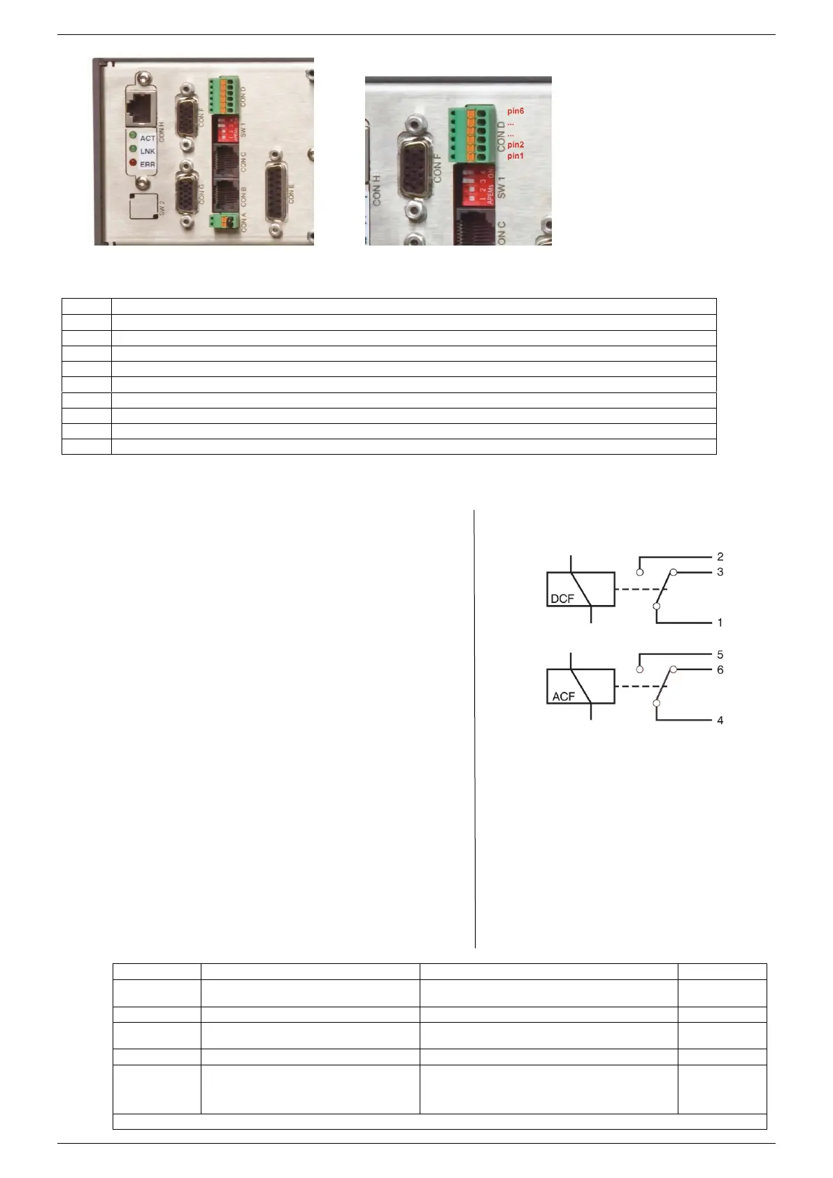
fig 3 - 10
Status relay outputs on CON D. This situation gives
the relay positions during fault condition.
fig 3 – 8 Location of output terminals and analog
programming connector on the rear panel.
Master connector for Master / Slave operation (output)
Slave connector for Master / Slave operation (input)
Relay Outputs, contacts 1 - 6
Analog Programming Connector ( not available when the optional ISO AMP or PSC-488 is installed, see CON H)
PSC-232, from PC or previous PSC (optional)
PSC-232, to next PSC (optional)
PSC-488 (optional) or ISO AMP CARD (optional) instead of CON E.
Various settings, see table at the bottom of this page.
Settings for PSC-488 and PSC-232 (optional)
fig 3 -9 Connectors and switches on the rear panel.
Programming via 15pole connector CON E
(analog).
Optional programming with e.g. PSC-232, PSC-488,
ISO AMP CARD
‘Output On’ after mains on
‘Output Off’ after mains on
DCF LED disabled
(DCF status and DCF relay are still enabled)
Parallel Master / Slave operation
Series Master / Slave operation
After switching mains on, the unit will start with
the same settings for the voltage and the
current as it had before switching mains off
After switching mains on, the unit will always start up
with a voltage setting of 0 V and a current setting of 0
A. Once the unit is switched on, the voltage and current
can be set to the preferred value.
* = SW1-5 only on units with optional digital encoders (option P220).
 Loading...


