TROUBLE SHOOTING SM1500
19 / 22 DELTA ELEKTRONIKA B.V. rev. Jan. 2021
MASTER / SLAVE PARALLEL PROBLEMS
Check the voltage drop of the wiring between the master and
the slaves is < 10 mV.
Check the wiring has a low inductance.
5.7
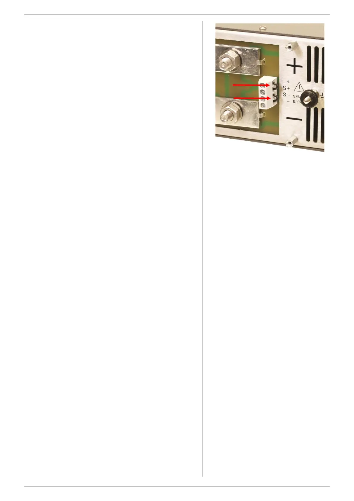
DC OUTPUT VOLTAGE IS HIGHER THAN SET
VALUE
Check connections on SENSE BLOCK (on rear panel), For
normal operation there should be a link between + and S+
and between – and S– (see also fig. 5 - 3). When remote
sensing is used, check the wires of the sensing.
5.8
The temperature of the internal heat sink is too high, the
output has been shutdown to avoid overheating.
Check if the cooling fans are running.
Check if the air temperature of the air inlets (left) is below
50 °C and the airflow is not obstructed.
5.9
The temperature of the internal heat sink is getting too high, a
further increase will shutdown the power supply.
Check if the cooling fan is running properly.
Check if the air temperature of the air inlet (left) is below
50 °C and the airflow is not obstructed.
5.10
The input voltage is too low or was intermittent because of a
bad connection. Disconnect the mains, wait a few minutes
and try again.
Note the following:
As soon as the ACF LED is on, the settings for Remote CV,
Remote CC and Keylock will be saved. If the unit turns back
on, it will have the same settings. For the setting of Output
On/Off after turning the unit back on, the position of DIP
switch 2 on SW1 is determining.
If the ACF situation lasts a few seconds, the output will
shutdown. The ACF problem has to be solved first, before the
output can be turned on again.
Internal error, send unit for repair. See paragraph 1).
5.11
The output voltage is below the set voltage. This
automatically happens when the unit is in CC-mode (CC LED
is on).
Also with an interrupted Interlock connector, the DCF LED will
be on.
Internal error, send unit for repair. See paragraph 1).
5.12
The Power Sink is in overload or the temperature of the
Power Sink is too high. See datasheet of the Power Sink
option for further details.
5.13
Blinking LEDs REMOTE CV, REMOTE CC and
OUTPUT ON
This indicates the Keylock function is activated, see previous
paragraph 5) in "operating manual".
5.14
Do not try to repair, but send for repair. See paragraph 1).
5.15
If the problem persists, please fill out the RMA-form on our
website www.DeltaPowerSupplies.com. See previous
paragraph 1).
fig 5 - 3
For normal operation links should be connected
between S+ and +, and between S- and -.
 Loading...


